


5
English
ALWA
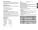
YSADJUSTFENCE
PROP
ERLYBEFOREUSE
DW7050
DW7051
SELF-TAPPING
STUD
LOCKNUTS
END PLATE
CLAMPING BRACKET
STOP
WASHER
AND SCREW
KNOBS
BOTTOM
HOLE
(USE IF ON
RIGHT SIDE)
BRACKET
TOP HOLE
(USE IF ON
LEFT SIDE)
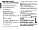
As shown in Figure 6 the inner clamp washer is installed
first, then the blade adapter. The blade adapter is
designed to permit the use of saw blades with 1" arbor
holes as well as those with 5/8" arbor holes.
When using blades with 1" arbor holes, install the blade
adapter over the spindle shaft and against the inner
clamp washer, as shown in the figure. Next, install the
saw blade making sure that the arbor hole in the blade
fits on the blade adapter. Make sure that the teeth at the
bottom of the blade are pointing toward the back of the
saw (away from the operator). Install the outer clamp
washer and install the blade screw. Tighten firmly using
the spindle lock and the provided wrench (left hand
threads). When using saw blades with 5/8" arbor holes,
remove the blade adapter! Save it in a safe place for
future use. The rest of the blade assembly is exactly the
same.
NEVER DEPRESS THE SPINDLE LOCK PIN WHILE
THE BLADE IS ROTATING.
BE SURE TO HOLD THE GUARD BRACKET DOWN
AND FIRMLY TIGHTEN THE GUARD BRACKET
SCREW WHEN YOU FINISH INSTALLING THE SAW
BLADE. FAILURE TO DO SO WILL CAUSE SERIOUS
DAMAGE TO THE SAW.
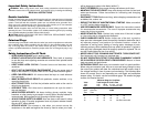
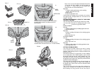
Installing Extension Kit
Side Table Extension (Some Models)
BE SURE TO OBSERVE ALL OF THE SAFETY
INSTRUCTIONS IN YOUR MITER SAW INSTRUCTION
MANUAL.
UNPLUG THE MITER SAW BEFORE INSTALLING,
ADJUSTING OR REMOVING THE EXTENSION KIT.
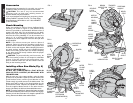
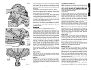
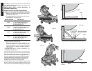
The extension kit can be used on either or both sides of
the saw. The supplied extension kit is factory installed on
the left side:
1. Install the self-tapping stud into the hole underneath
the saw.
2. Install extension tube as shown (Fig. 2) making sure
the clamping bracket will catch the legs.
3. Tighten clamping bracket against the legs.
WARNING: Do not lift, support, or carry the miter saw
by the extension kit. To do so may cause tipping and loss
of control, leading to personal injury. NOTE: Before
transporting the saw, remove the extension or telescope
it into the base.
Rear Lower Guard Adjustment
Check the rear lower guard to ensure that it is located
such that the saw blade is in the center and equidistant
from each side, as shown in Figures 6 & 7. Adjust as
necessary by loosening the two screws and moving the
guard. Firmly tighten both screws. Never remove this
guard.
Transporting the Saw
TURN OFF AND UNPLUG THE MITER SAW BEFORE
ATTEMPTING TO MOVE IT OR MAKE ANY
ADJUSTMENTS WHAT-SO-EVER!
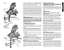
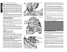
In order to conveniently carry the miter saw from place to
place, a carrying handle has been included on the top of
the saw arm, as shown in Figure 3. To transport the saw,
lower the arm and depress the lock down pin shown in
Figure 4.
Adjustments
PERFORM ALL ADJUSTMENTS WITH THE MITER
SAW UNPLUGGED
NOTE: Your miter saw is fully and accurately adjusted at
the factory at the time of manufacture. If readjustment
due to shipping and handling or any other reason is
required, follow the steps below to adjust your saw.
Once made, these adjustments should remain accurate.
Take a little time now to follow these directions carefully
to maintain the accuracy of which your saw is capable.
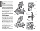
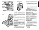
MITER SCALE ADJUSTMENT –
Place a square against the saw’s fence and blade, as
shown in Figure 8. (Do not touch the tips of the blade
teeth with the square. To do so will cause an inaccurate
measurement.) Loosen the miter clamp knob (see Fig. 9)
and swing the miter arm until the miter latch locks it at
the 0 miter position. Do not tighten the clamp knob. If the
saw blade is not exactly perpendicular to the fence,
loosen the three screws that hold the miter scale to the
base (shown in Fig. 9) and move the scale/miter arm
assembly left or right until the blade is perpendicular to the
fence, as measured with the square. Retighten the three
screws. Pay no attention to the reading of the miter pointer
at this point.
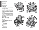
MITER POINTER ADJUSTMENT
Loosen the miter clamp knob and squeeze the miter
latch to move the miter arm to the zero position, as
shown in Figure 9. With the miter clamp knob loose allow
the miter latch to snap into place as you rotate the miter
arm past zero. Observe the pointer and miter scale
through the viewing opening shown in Figure 10. If the
pointer does not indicate exactly zero, gently pry it left or
right using a flat bladed screwdriver.
BEVEL SQUARE TO TABLE
To align the blade square to the rotary table, lock the
arm in the down position. Place a square against the
blade taking care to not have the square on top of a
tooth, as shown in Figure 11B. Loosen the Bevel Clamp
Knob so that you can move the Bevel Arm. Move the
Bevel Arm as necessary so that the blade is at zero
degrees bevel to the table. If the Bevel Arm needs
adjustment, loosen the lock nut on the right side Bevel
SINGLE PIECE
SUPPLIED
EXTENSION
(SOME MODELS)