


English
6
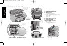
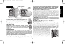
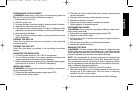
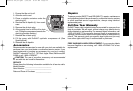
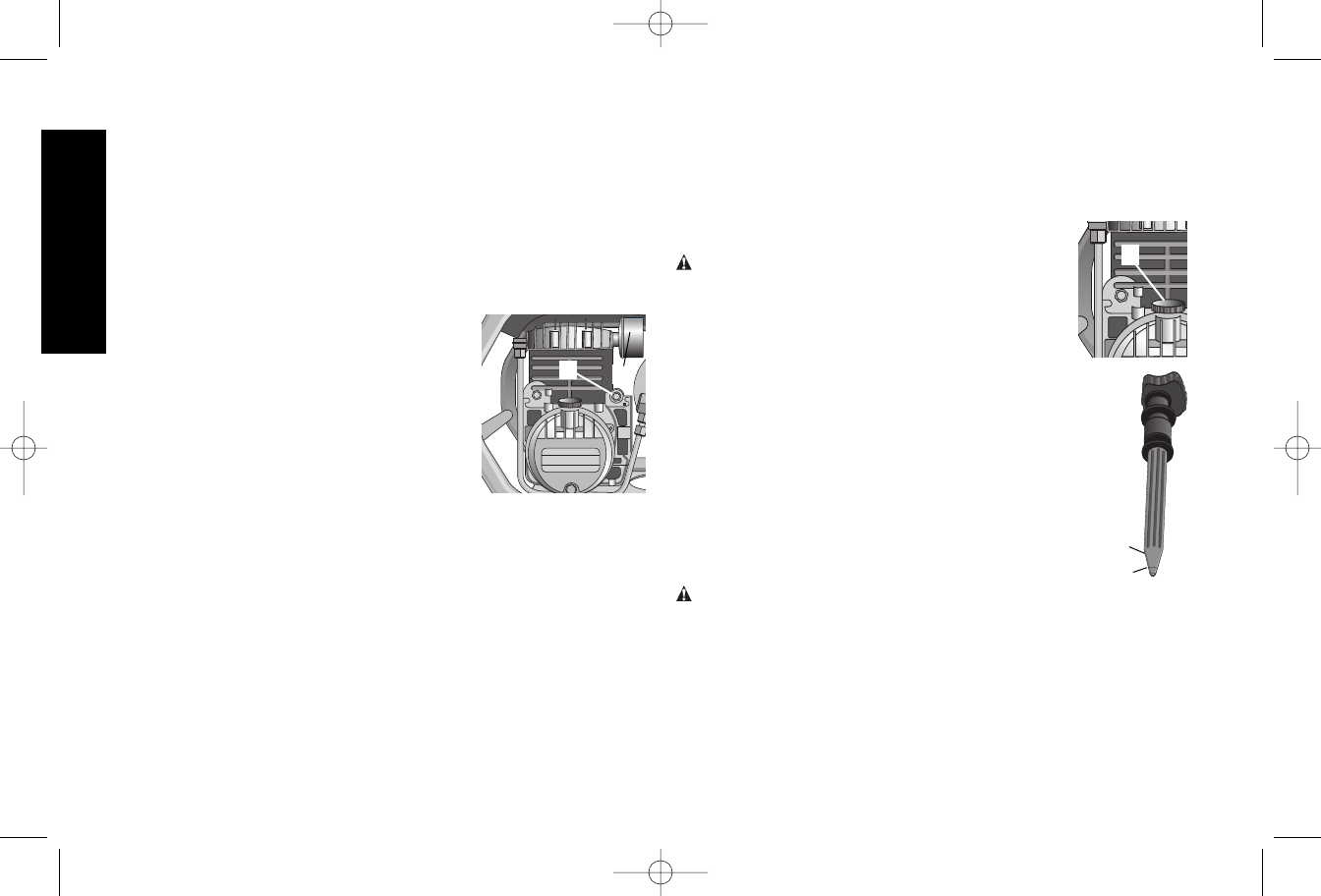
OIL DIPSTICK
The dipstick (H) will indicate the amount of oil in the pump. Oil level should
be checked on a daily basis to ensure that it does not exceed the maximum
notch or fall below the minimum notch on the dipstick.
Common Procedures
CHECKING COMPRESSOR PUMP OIL LEVEL
WARNING: Aftercooler, pump head, and
surrounding parts are very hot. Do not touch. (see
Hot Surfaces on page 4).
1. Ensure that the unit is off.
2. Locate unit on a flat horizontal surface.
3. Remove dipstick (H) from oil fill port.
4. Look for visual signs of contaminants (water, dirt,
etc.) in oil on dipstick.
5. Wipe oil off of the dipstick.
6. Reinsert the dipstick fully into the oil fill port for a few
seconds to allow oil to collect on dipstick.
7. Remove the oil dipstick to read oil level. Oil should
not exceed top raised line (MAX) on dipstick. If oil is
below lower mark (MIN), add D
EWALT synthetic oil
and follow steps 5 through 7.
CHECKING SAFETY RELIEF VALVE OPERATION
WARNING: Aftercooler, pump head, and surrounding
parts are very hot. Do not touch (see Hot Surfaces on page 4).
1. Ensure that the unit is off.
2. Ensure that the tank is empty by looking at tank pressure gage.
Drain the tanks if necessary.
3. Grasp the wire ring on the safety valve.
4. Pull and release the ring a few times to ensure that the plunger
moves in and out. Replace the safety valve if plunger does not
move or is difficult to move.
SAFETY RELIEF VALVE
This valve (B) is designed to prevent system failures by relieving
pressure from the system when the compressed air reaches a
predetermined level. The valve is preset by the manufacturer and
must not be modified in any way.
AIR TANK DRAIN VALVE
The drain valve is used to remove moisture from the air tank after the
air compressor is shut off.
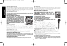
MOTOR THERMAL OVERLOAD
The electric motor has a manual thermal
overload protector (C). If the motor overheats
for any reason, the thermal overload will cut
off power, thus preventing the motor from
being damaged. Turn the pressure switch to
the OFF position and wait until the motor
cools before pressing the thermal overload
button.
AIR INTAKE FILTER
This filter (D) is designed to clean air entering the pump. To ensure
the pump continually receives a clean, cool, and dry air supply this
filter must always be clean and the filter intake must be free from
obstructions.
TANK PRESSURE GAGE
The tank pressure gage indicates air pressure in the air tank.
REGULATED PRESSURE GAGE
The regulated pressure gage indicates the air pressure available at the
outlet side of the regulator. This pressure is controlled by the regulator and
is always less than or equal to the air tank pressure.
PRESSURE REGULATOR
The regulator knob controls the air pressure coming from the air tank.
MAX
H
MIN
C
D
5135175-02,01.qxd 3/30/05 8:32 PM Page 6