


7
English
Adjustments
PERFORM ALL ADJUSTMENTS WITH THE SLIDING
COMPOUND MITER SAW UNPLUGGED.
NOTE: Your sliding compound miter saw is fully and accu-
rately adjusted at the factory at the time of manufacture. If
readjustment due to shipping and handling or any other
reason is required, follow the steps below to adjust your saw.
Once made, these adjustments should remain accurate.
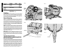
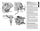
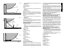
MITER SCALE ADJUSTMENT
Place a square against the saw’s base, fence and blade, as
shown in Figure 7. (Do not touch the tips of the blade teeth
with the square. To do so will cause an inaccurate measure-
ment.) Lift the miter clamp handle and swing the miter arm
until the miter latch locks it at the 0 miter position. If the saw
blade is not exactly perpendicular to the fence, loosen the four
screws that hold the miter scale to the base (shown in Figure
10) and move the scale/miter arm assembly left or right until
the blade is perpendicular to the fence, as measured with the
square. Retighten the four screws. Pay no attention to the
reading of the miter pointer at this time.
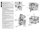
MITER POINTER ADJUSTMENT
Lift the miter adjustment/lock handle and move the miter arm
to the zero position, as shown in Figure 8. With the miter
adjustment/lock handle loose allow the miter latch to snap into
place as you rotate the miter arm to zero. Observe the pointer
and miter scale. If the pointer does not indicate exactly zero,
loosen the screw that holds the pointer in place and gently
move the pointer left or right. Retighten the screw after setting
the pointer to zero.
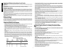
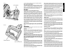
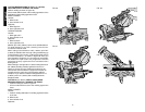
MITER LOCK/DETENT ROD ADJUSTMENT
The miter lock/detent rod should be adjusted if the table of the
saw can be moved when the miter adjustment/lock handle is
locked-down.
To adjust the miter lock/detent rod, put the miter adjust-
ment/lock handle in the up, unlocked position. Using a slotted
screwdriver, tighten the lock rod by turning it clockwise (Figure
9). Turn the lock rod until it is tight, then turn counterclockwise
1/4 turn. To ensure the lock handle is functioning properly, re-
lock the miter lock to a non-detented measurement on the
miter scale—for example, 34°—and ensure the table will not
rotate.
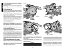
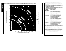
BEVEL STOPS AND POINTER ADJUSTMENT
Adjusting the bevel stop and pointer to 0°
Place the saw in the up position (0° bevel). Push head fully
back (toward fence) and lock the rail lock knob. Place a square
against the saw’s base, fence and blade (Figure 12). (Do not
touch the tips of the blade teeth with the square. To do so will
cause an inaccurate measurement.) Loosen the bevel lock
handle so bevel movement is snug, but not fully loose.
Push head of saw to the right (to contact the 0° bevel stop).
Adjust the 0˚ bevel stop screw (Figure 13) until the blade is
perpendicular to the base of the saw. Tighten the bevel lock
handle securely. Make sure the bevel pointer indicates 0°
exactly. If it does not, loosen the screw that holds the pointer
FIG.9
FIG. 10
FIG. 11
FIG. 12
MITER SCALE SCREW
MITER
LOCK/DETENT
ROD
RIGHT BEVEL
STOP SCREW