


16
English
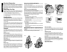
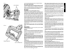
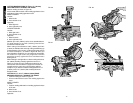
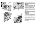
To adjust the tension, loosen, but do not remove, the six
screws (Figure 39). Then rotate the set screw on the top of
the motor plate casting until the proper tension is achieved.
Tighten the six screws securely and replace the belt cover.
NOTE: Overtightening the belt will cause premature motor
failure.
Maintenance
1. All bearings are sealed ball bearings. They are lubricated
for life and need no further maintenance. Do not use WD-
40 or any other lubricant.
2. Periodically clean all dust and wood chips from around the
area of the saw. Even though slots are provided to allow
debris to pass through, some dust will accumulate.
3. The brushes are designed to give you several years of
use. If they ever need replacement follow the instructions
on page 9 or return the tool to the nearest service center
for repair. Service center locations are packed with your
tool.
Important
To assure product SAFETY and RELIABILITY, repairs,
maintenance and adjustment (including brush inspection
and replacement) should be performed by authorized service
centers or other qualified service organizations, always using
identical replacement parts.
Full Warranty
D
EWALT heavy duty industrial tools are warranted for one
year from date of purchase. We will repair, without charge,
any defects due to faulty materials or workmanship. For
warranty repair information, call 1-800-4-D
EWALT. This
warranty does not apply to accessories or damage caused
where repairs have been made or attempted by others. This
warranty gives you specific legal rights and you may have
other rights which vary in certain states or provinces.
In addition to the warranty, D
EWALT tools are covered by our:
30 DAY NO RISK SATISFACTION GUARANTEE
If you are not completely satisfied with the performance of
your D
EWALT heavy duty industrial tool, simply return it to the
participating seller within 30 days for a full refund. Please
return the complete unit, transportation prepaid. Proof of
purchase may be required
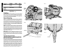
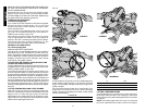
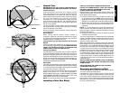
FIG. 36
CENTER BOSS
SET
SCREW
SPINDLE
LOCK
SCREWS
FIG. 37
FIG. 38
FIG. 39
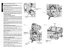
THUMBSCREW
GROOVING LEVER