


11
English
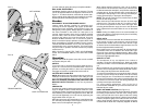
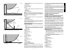
VERNIER SCALE
Your saw is equipped with a vernier scale for added precision.
The vernier scale allows you to accurately set miter angles to
the nearest 1/4 degree. To use the vernier scale follow these
steps.
(As an example, assume that the angle you want to miter is
24-1/4 degree right).
1. Turn off sliding compound miter saw.
2. Set the miter angle to the nearest whole degree desired by
aligning the center mark in the vernier scale, shown in
Figure 24, with the whole degree number etched in the
miter scale. Examine Figure 24 closely; the setting shown
is 24 degrees right miter.
3. To set the additional 1/4 degree, move the first mark on the
right to the right until the 1/4 degree vernier mark aligns
with the CLOSEST degree mark on the miter scale. In our
example, the closest degree mark on the miter scale
happens to be 25 degrees. Figure 25 shows a setting of 24-
1/4 degrees right miter.
4. To set a 1/2 degree, align the second mark on the scale
(marked 0.5) with the nearest whole degree number. For
example, to miter 24-1/2 degrees to the right, move the
SECOND mark on the RIGHT of the diamond to the
RIGHT until the 1/2 degree vernier mark aligns with the
CLOSEST degree mark on the miter scale.
5. To set a 3/4 degree, align the THIRD mark on the scale
with the nearest whole degree number. For example, to
miter 24-3/4 degrees to the right, move the THIRD mark
on the RIGHT of the diamond to the RIGHT until the 3/4
degree vernier mark aligns with the CLOSEST degree
mark on the miter scale.
WHEN MITERING TO THE RIGHT
To increase the miter angle when mitering to the right, move
the arm to align the appropriate vernier mark with the closest
mark on the miter scale to the right. To decrease the miter
angle when mitering to the right, move the arm to align the
appropriate vernier mark with the closest mark on the miter
scale to the left.
WHEN MITERING TO THE LEFT
To increase the miter angle when mitering to the left, move
the arm to align the appropriate vernier mark with the closest
mark on the miter scale to the left. To decrease the miter
angle when mitering to the left, move the arm to align the
appropriate vernier mark with the closest mark on the miter
scale to the right.
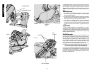
CUTTING BASE MOLDING
ALWAYS MAKE A DRY RUN WITHOUT POWER BEFORE
MAKING ANY CUTS.
Straight 90 degree cuts –
Position the wood against the fence and hold it tightly to the
fence and table, as shown in Figure 26. Turn on the saw,
allow the blade to reach full speed and lower the arm
smoothly through the cut.
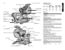
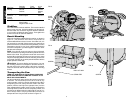
FIG. 20
A.
B.
FIG. 21
FIG. 22
ANGLE “A”
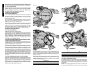
ment/lock handle are securely tightened. These handles must
be tightened and locked after making any changes in bevel or
miter.
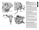
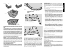
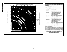
The chart shown on page 14 will assist you in selecting the
proper bevel and miter settings for common compound miter
cuts. To use the chart, select the desired angle “A” (Table 1)
of your project and locate that angle on the appropriate arc in
the chart. From that point follow the chart straight down to find
the correct bevel angle and straight across to find the correct
miter angle. Once again, position the wood with the broad
flat side on the table and the narrow edge against the fence.
Set your saw to the prescribed angles and make a few trial
cuts. Practice fitting the cut pieces together until you develop a
feel for this procedure and feel comfortable with it.
Example: To make a 4 sided box with 26° exterior angles
(Angle A, Figure 22), use the upper right arc. Find 26° on the
arc scale. Follow the horizontal intersecting line to either side
to get miter angle setting on saw (42°). Likewise, follow the
vertical intersecting line to the top or bottom to get the bevel
angle setting on the saw (18°). Always try cuts on a few scrap
pieces of wood to verify settings on saw.
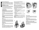
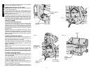
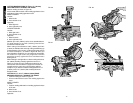
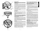
DUAL RANGE MITER SCALE
The miter scale has two ranges of numbers for convenience,
as shown in Figure 23. One scale indicates 0 degrees when
the blade is square to the fence. At this position the other scale
reads 90 degrees.
FIG. 23
FIG. 24
The 0 degree scale (larger numbers closer to the front edge) is
used when calculating angles. To calculate the proper miter
angle, divide 180 degrees by the number of sides of the box or
frame.
The 90 degree scale (smaller numbers behind the zero
degree scale) is used when a corner of your box or frame is
measured with a protractor. For example: if you measure the
corner of an 8 sided box, the protractor will read 135 degrees.
To determine the proper miter setting, divide the measured
angle by two. The proper miter setting in this example is 67-1/2
degrees. Set this angle on the 90 degree scale. This is most
useful when a corner is at an odd angle.
CENTER MARK
DUAL RANGE MITER
SCALE
FIG. 25