


English
8
The blade guard on your saw has been designed to automatically raise when the arm is
brought down and to lower over the blade when the arm is raised.
The guard can be raised by hand when installing or removing saw blades or for inspection of
the saw. NEVER RAISE THE BLADE GUARD MANUALLY UN LESS THE SAW IS TURNED
OFF.
NOTE: Certain special cuts of large material will require that you manually raise the guard.
Refer to Cutting Large Material under Special Cuts.
The front section of the guard is louvered for visibility while cutting. Although the louvers
dramatically reduce flying debris, they are openings in the guard and safety glasses should
be worn at all times when viewing through the louvers.
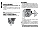
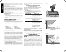
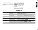
MITER LOCK ADJUSTMENT (FIG. 9)
The miter lock rod should be adjusted if the table of the saw can be moved when the
miter lock handle is locked down. To adjust, put the miter lock handle in the up position.
Using a slotted screwdriver, adjust the lock rod in 1/8 clockwise turn increments to
increase the lock force. To ensure the miter lock is functioning properly, re-lock miter lock
handle to a non-detent miter angle.
FIG. 9
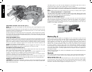
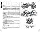
Brushes (Fig. 2)
Inspect carbon brushes regularly by unplugging the tool, removing the motor end cap
(Fig. 2) and removing the brush cap that holds the spring-loaded brush assembly. Keep
brushes clean and sliding freely in their guides. Always replace a used brush in the
same orientation in the holder as it was prior to its removal. If the brush is worn down to
approximately 1/2" (12.7 mm), the spring will no longer exert pressure and they must be
replaced. Use only identical D
EWALT brushes. Use of the correct grade of brush is essential
for proper operation of electric brake. New brush assemblies are available at D
EWALT
service centers. The tool should be allowed to “run in” (run at no load) for 10 minutes before
use to seat new brushes. The electric brake may be erratic in operation until the brushes
are properly seated (worn in). Always replace the brush inspection cap after inspection or
servicing the brushes.
While “running in” DO NOT TIE, TAPE, OR OTHER WISE LOCK THE TRIGGER SWITCH ON.
HOLD BY HAND ONLY.
Controls
Your compound miter saw has several main controls, which will be discussed briefly here.
For more information on these controls, see the respective sections later in the manual.
MITER CONTROL (FIG. 5, 10)
The miter lock lever (J) and miter latch (K) allows you to miter your saw 50° left and right.
To miter the saw, unlock miter lock lever (J) by pulling upward, squeeze the detent trigger
(K) and set the miter angle desired on the miter scale. Lock miter lock handle by pressing
downward. Override the detent trigger by rotating knob (Fig. 10, V).
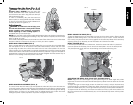
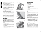
FIG. 8
L
S
R
R
P
U
O
N
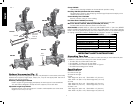
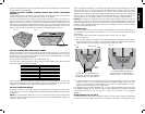
ADJUSTING THE BEVEL STOP TO 33.9º (FIG. 8)
NOTE: Adjust the 33.9º bevel angles only after performing the 0º bevel angle and pointer
adjustment.
To set the 33.9º bevel angle, flip out the stop pawls (P). Loosen the bevel lock knob (L) and tilt
the head to the left. If the pointer does not indicate exactly 33.9º, turn the screw contacting
the pawl until the pointer reads 33.9º.
To adjust the right 33.9º bevel angle, flip out the stop pawl. Loosen the bevel lock knob (L)
and pull the bevel stop override button (S) to override the 0º bevel stop. When the saw is fully
to the right, if the pointer does not indicate exactly 33.9º, turn the screw contacting the pawl
until the pointer indicates 33.9º.
FENCE ADJUSTMENT (FIG. 8)
In order that the saw can bevel to a full 48° left or right, the fences can be adjusted to provide
clearance. To adjust a fence, loosen the plastic knob (Figure 8, R), and slide the fence outward.
Make a dry run with the saw turned off and check for clearance. Adjust the fence to be as
close to the blade as practical to provide max imum workpiece support, without interfering
with arm up and down movement. Tighten knob securely. When the bevel operations are
complete, don’t forget to relocate the fence.
NOTE: The guide groove of the fences can become clogged with sawdust. If the guide
groove becomes clogged, use a stick, low pressure air or a vacuum to clear.
AUTOMATIC ELECTRIC BRAKE (FIG. 2)
Your saw is equipped with an automatic electric blade brake which stops the saw blade
within 5 seconds of trigger release. This is not adjustable.
On occasion, there may be a delay after trigger release to brake engagement. On rare
occasions, the brake may not engage at all and the blade will coast to a stop.
If a delay or “skipping” occurs, turn the saw on and off 4 or 5 times. If the condition persists,
have the tool serviced by an authorized D
EWALT service center.
Always be sure the blade has stopped before removing it from the kerf plate. The brake is not
a substitute for guards. Ensure your own safety by giving the saw your complete attention.
GUARD ACTUATION AND VISIBILITY
CAUTION: Pinch Hazard. To reduce the risk of injury, keep thumb underneath the handle
when pulling the handle down. The lower guard will move up as the handle is pulled down
which could cause pinching.