


English
6
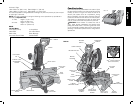
Press down lightly on the operating handle and pull out the lock down pin, as shown in Figure 2.
Gently release the downward pressure and hold the arm allowing it to rise to its full height. Use
the lock down pin when carrying the saw from one place to another. Always use the carrying
handle to transport the saw or the hand indentations shown in Figure 2 and 4.
ASSEMBLY AND ADJUSTMENTS
WARNING: To reduce the risk of injury, turn unit off and disconnect it from power
source before installing and removing accessories, before adjusting or when
making repairs. An accidental start-up can cause injury.
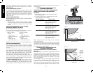
Bench Mounting
Holes are provided in all four feet to facilitate bench mounting, as shown in Figure 2. (Two
different sized holes are provided to accommodate different sizes of screws. Use either hole,
it is not necessary to use both.) Always mount your saw firmly to a stable surface to prevent
movement. To enhance the tool’s portability, it can be mounted to a piece of 1/2" (12.7 mm)
or thicker plywood which can then be clamped to your work support or moved to other job
sites and reclamped.
NOTE: If you elect to mount your saw to a piece of plywood, make sure that the mounting
screws don’t protrude from the bottom of the wood. The plywood must sit flush on the work
support. When clamping the saw to any work surface, clamp only on the clamping bosses
where the mounting screw holes are located. Clamping at any other point will surely interfere
with the proper operation of the saw.
CAUTION: To prevent binding and inaccuracy, be sure the mounting surface is not warped
or otherwise uneven. If the saw rocks on the surface place a thin piece of material under one
saw foot until the saw sits firmly on the mounting surface.
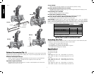
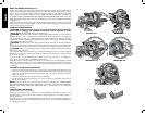
Changing or Installing a New Saw Blade (Fig. 3)
CAUTION:
• Never depress the spindle lock button while the blade is under power or coasting.
• Do not cut ferrous metal (containing iron or steel) or masonry or fiber cement product
with this miter saw.
FIG. 3
A
B
D
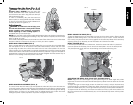
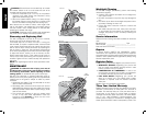
Removing the Blade
1. Unplug the saw.
2. Raise the arm to the upper position and raise the lower guard (A) as far as possible.
3. Loosen, but do not remove guard bracket screw (B) until the bracket can be raised far
enough to access the blade screw. Lower guard will remain raised due to the position of
the guard bracket screw.
4. Depress the spindle lock button (C) while carefully rotating the saw blade by hand until the
lock engages.
5. Keeping the button depressed, use the other hand and the wrench provided (D) to loosen
the blade screw. (Turn clockwise, left-hand threads.)
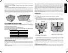
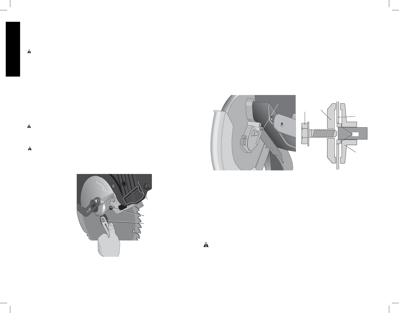
6. Remove the blade screw (E), outer blade clamp (F), and blade (G). The inner blade clamp
(I), and if used, the 1" (25.4 mm) blade adapter (H), may be left on the spindle.
NOTE: For blades with a blade hole of 5/8" (15.88mm), the 1" (25.4mm) blade adapter
is not used.
E
F
G
H
FIG. 3B
I
C
FIG. 3A
Installing a Blade
1. Unplug the saw.
2. With the arm raised, the lower guard held open and the guard bracket raised, place
the blade on the spindle, onto the blade adapter [if using a blade with a 1" (25.4mm)
diameter blade hole] and against the inner blade clamp with the teeth at the bottom of
the blade pointing toward the back of the saw.
3. Assemble the outer blade clamp onto the spindle.
4. Install the blade screw (E) and, engaging the spindle lock, tighten the screw firmly with
wrench provided. (Turn counterclockwise, left-hand threads.)
NOTE: When using blades with a 5/8" (15.88 mm) diameter blade hole, the blade adapter will
not be used and should be stored in a safe place for future use.
5. Return the guard bracket to its original position and firmly tighten the guard bracket
screw (B) to hold bracket in place.
WARNING:
• The guard bracket must be returned to its original position and the screw
tightened before activating the saw.
• Failure to do so may allow the guard to contact the spinning saw blade
resulting in damage to the saw and severe personal injury.