


English
7
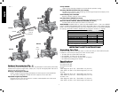
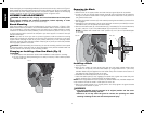
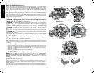
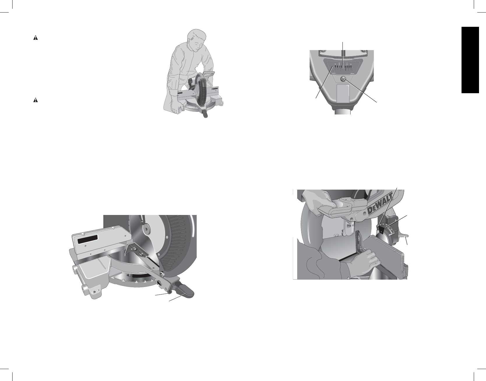
Transporting the Saw (Fig. 2, 4)
FIG. 4
WARNING: To reduce the risk of serious
personal injury, ALWAYS lock the miter lock
handle, bevel lock knob, fence adjustment knobs,
and secure the arm down using the lock down pin
before transporting saw.
In order to conveniently carry the miter saw from
place to place, a carrying handle has been included
on the top of the saw arm and hand indentations in
the base, as shown in Figures 2, 4.
Adjustments
WARNING: To reduce the risk of injury, turn
unit off and disconnect it from power source
before installing and removing accessories,
before adjusting or when making repairs. An
accidental start-up can cause injury.
NOTE: Your miter saw is fully and accurately adjusted at the factory at the time of manufacture.
If readjustment due to shipping and handling or any other reason is required, follow the steps
below to adjust your saw.
Once made, these adjustments should remain accurate. Take a little time now to follow these
directions carefully to maintain the accuracy of which your saw is capable.
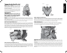
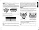
MITER SCALE ADJUSTMENT (FIG. 5)
Place a square against the saw’s fence and blade. (Do not touch the tips of the blade teeth
with the square. To do so will cause an inaccurate measure ment.) Unlock miter lock lever
(J) and swing the miter arm until the miter latch locks it at the 0 miter position. Do not lock
miter lock lever (J). If the saw blade is not exactly perpendicular to the fence, loosen the three
screws that hold the miter scale to the base and move the scale left or right until the blade is
perpendicular to the fence, as measured with the square. Retighten the three screws. Pay no
attention to the reading of the miter pointer at this time.
FIG. 5
J
K
MITER POINTER ADJUSTMENT (FIG. 5, 6)
To unlock, lift the miter lock lever (J) up and squeeze the miter latch (K) to move the miter arm
to the zero position. With the miter lock lever unlocked allow the miter latch to snap into place
as you rotate the miter arm to zero. Observe the pointer and miter scale through the viewing
opening shown in Figure 6. If the pointer does not indicate exactly zero, loosen the screw
holding the pointer in place, reposition the pointer and tighten the screw.
FIG. 6
MITER
SCALE
POINTER
POINTER
ADJUSTMENT
SCREW
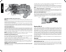
BEVEL SQUARE TO TABLE (FIG. 7)
To align the blade square to the rotary table, lock the arm in the down position. Place a square
against the blade taking care to not have the square on top of a tooth. Loosen the bevel
lock knob (L) and ensure the arm is firmly against the 0º bevel stop. Move the 0º bevel stop
adjusting screw (T) as necessary so that the blade is at 0º bevel to the table.
BEVEL POINTER (FIG. 7)
If the bevel pointer (M) does not indicate zero, loosen the screw that holds it in place and
move the pointer as necessary. Do not remove the steel plate in front of the bevel pointer.
This plate prevents wood resin from accumulating on the bevel scale during use.
FIG. 7
T
L
M
ADJUSTING THE BEVEL STOP TO 45º LEFT OR RIGHT (FIG. 8)
NOTE: Adjust the 45º bevel angles only after performing the 0º bevel angle and pointer
adjustment. Ensure the 45º bevel override levers (N) are pushed inward to obtain an accurate
adjustment.
To adjust the right 45º bevel angle, loosen the bevel lock knob (L) and pull the bevel stop
override knob (S) to override the 0º bevel stop. When the saw is fully to the right, if the pointer
does not indicate exactly 45º, turn the right bevel stop screw (O) until the pointer indicates 45º.
To adjust the left 45º bevel stop, first loosen the bevel lock knob (L) and tilt the head to the
left. If the pointer does not indicate exactly 45º, turn the left bevel stop screw until the pointer
reads 45º.