


61
English
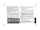
injury. Threaded accessories must have a 5/8"–11 (B3) & M14 (AR,
B2, B2C, BR) hub. Every unthreaded accessory must have a 7/8"
(22.2 mm) arbor hole. If it does not, it may have been designed for a
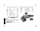
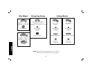
circular saw. Use only the accessories shown on pages 62–64 of this
manual. Accessory ratings must always be above tool speed as
shown on tool nameplate.
Mounting Guard
CAUTION: Guards must be used with all grinding wheels,
cutting wheels, sanding flap discs, wire brushes, and wire
wheels. The tool may be used without a guard only when sanding
with conventional sanding discs. A Type 1 guard is available at
extra cost from your local dealer or authorized service center.
Grinding and cutting with wheels other than Type 27 and 29
require different accessory guards not included with tool. A Type27
guard is provided for use with the Type 27 wheel. Mounting
instructions for accessory guards are shown below and are also
included in the accessory package.
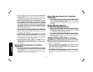
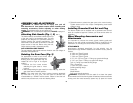
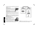
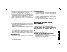
MOUNTING AND REMOVING GUARD (FIG. 4, 5)
1. Open the guard latch (K), and align the lugs (L) on the guard with
the slots on the gear case (M). This will align the lugs on the guard
with the slots on the gear case cover.
K
L
M
FIG. 4
F
2. Push the guard down until the guard lugs engage and rotate freely
in the groove on the gear case hub.
3. With the guard latch open, rotate the guard (F) into the desired
working position. The guard body should be positioned between
the spindle and the operator to provide maximum operator
protection.
4. Close the guard latch to secure the guard on the gear case. You
should not be able to rotate the guard by hand when the latch is
closed. Do not operate the grinder with a loose guard or with the
guard latch in open position.
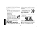
5. To remove the guard, follow the procedure above in reverse order.
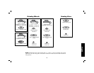
NOTE: The guard is pre-adjusted to the
N
FIG. 5
diameter of the gear case hub at the factory.
If, after a period of time, the guard becomes
loose, tighten the adjusting screw (N) with
guard latch in the closed position with guard
installed on the tool.
CAUTION: Do not tighten the adjusting
screw with the guard latch in the open
position. Undetectable damage to the guard
or the mounting hub may result.
CAUTION: If the guard cannot be tightened by the adjusting
clamp, do not use the tool. To reduce the risk of personal injury, take
the tool and guard to a service center to repair or replace the guard.
NOTE: Edge grinding and cutting can be performed with
Type 27 wheels designed and specified for this purpose; 1/4"
(6.35 mm) thick wheels are designed for surface grinding while 1/8"
(3.17 mm) wheels are designed for edge grinding. Cutting can also be
performed by using a Type 1 wheel and a Type 1 guard.
OPERATION
Switch (Fig. 6)
CAUTION: Before connecting the tool to a power source or after
a power failure, depress and release the trigger switch (A) once
without depressing the lock-on button (C) to ensure that the switch is
in the off position. If the trigger switch is locked on, the tool will start