


69
English
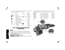
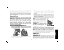
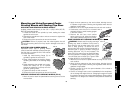
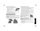
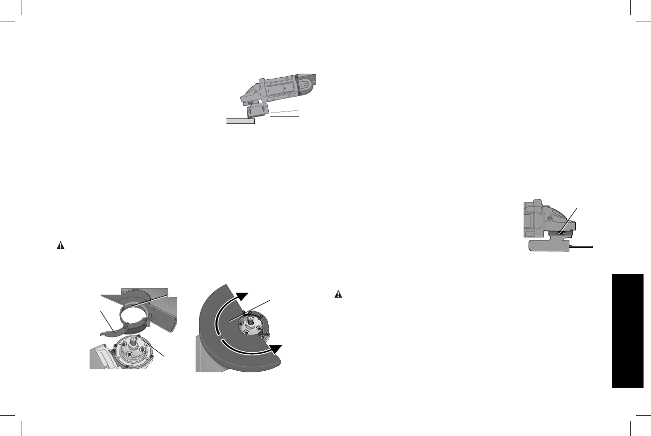
USING A FLARING CUP WHEEL (FIG. 17)
Flaring cup wheels are designed for heavy material removal.
1. Allow the tool to reach full speed before
5˚–10˚
FIG. 17
touching tool to work surface.
2. Apply minimum pressure to work
surface, allowing the tool to oper ate at
high speed.
3. Maintain a 5˚ to 10˚ angle between the
tool and the work surface.
4. Continuously move the tool in a forward and back motion to avoid
creating gouges in the work surface.
5. Remove the tool from work surface before turning tool off. Allow
the tool to stop rotating before setting it down.
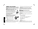
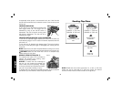
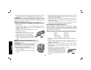
Mounting and Using Cutting
(Type 1) Wheels (Fig. 18, 19)
Cutting wheels include diamond wheels and abrasive discs. Abrasive
cutting wheels for metal and concrete use are available. Diamond
blades for concrete cutting can also be used.
WARNING: A closed, two-sided cutting wheel guard is included
with this tool and is re quired when using cutting wheels. Fail ure to use
proper flange and guard can re sult in injury resulting from wheel
breakage and wheel contact. See pages 62–64 for more information.
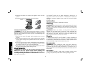
K
L
M
FIG. 18
F
MOUNTING CLOSED (TYPE 1) GUARD
1. Open the guard latch (K), and align the lugs (L) on the guard with
the slots on the hub (M). This will align the lugs with slots on the
gear case cover. Position the guard facing backward.
2. Push the guard down until the guard lug engages and rotates
freely in the groove on the gear case hub.
3. Rotate guard (F) into desired working position. The guard body
should be positioned between the spindle and the operator to
provide maximum operator protection.
4. Close the guard latch to secure the guard on the gear case cover.
You should be unable to rotate the guard by hand when the latch
is in closed position. Do not operate grinder with a loose guard or
with the guard latch in open position.
5. To remove the guard, follow the procedure above in reverse order.
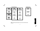
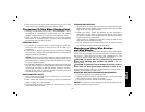
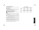
NOTE: The guard is pre-adjusted to the
FIG. 19
N
dia met er of the gear case hub at the factory.
If, after a period of time, the guard becomes
loose, tighten the adjusting screw (N) with
the guard latch in the closed position with
guard installed on the tool.
NOTICE: To reduce the risk of damage
to the tool, do not tighten adjusting screw with guard latch in open
position. Undetectable damage to guard or mounting hub may result.
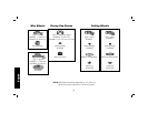
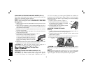
MOUNTING CUTTING WHEELS (FIG. 20)
CAUTION: Matching diameter threaded backing flange and clamp
nut (included with tool) must be used for cutting wheels.
1. Install wheel backing flange, aligning flats on spindle (T) with flats
on backing flange (O).
2. Place the wheel on the backing flange, centering the wheel on the
backing flange pilot.
3. Install the clamp nut, ensuring that the wheel remains centered on
the backing flange.