


62
English
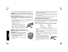
unexpectedly when power is reconnected to the tool. Hold the side
handle and rear handle firmly to maintain control of tool at start up and
during use.
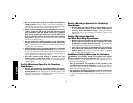
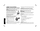
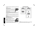
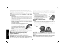
TRIGGER OPERATION
To turn the tool on, depress lock-off button (B)
A
B
C
FIG. 6
then trigger switch (A). The trigger can be
feathered as long as the lock-off button is
depressed. The tool will remain running while
the trigger is depressed. Turn the tool off by
releasing the trigger.
TRIGGER OPERATION WITH LOCK-ON FEATURE
To turn tool on, depress trigger. Depress and hold lock-on button (C)
while releasing trigger. Lock-on button will remain depressed and tool
will remain on.
To turn the tool off, depress and release trigger. The lock pin button
will pop out, permitting the trigger to disengage and causing the tool
to turn off.
NOTE: Allow the tool to reach full speed before touching tool to work
surface. Lift the tool from the work surface before turning the tool off.
CAUTION: Make sure the wheel has come to a complete stop
be fore setting the tool down.
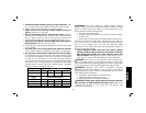
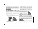
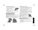
SPINDLE LOCK BUTTON (FIG. 7)
The spindle lock button (D) is provided to
FIG. 7
D
prevent the spindle from rotating when
installing or removing wheels.
NOTICE: To reduce the risk of damage to
the tool, do not engage the spindle lock
button while the tool is operating. Damage
to the tool will result and attached accessory
may spin off possibly resulting in injury.
To engage the lock, depress the spindle lock button (D) and rotate the
spindle until you are unable to rotate the spindle further.
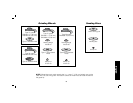
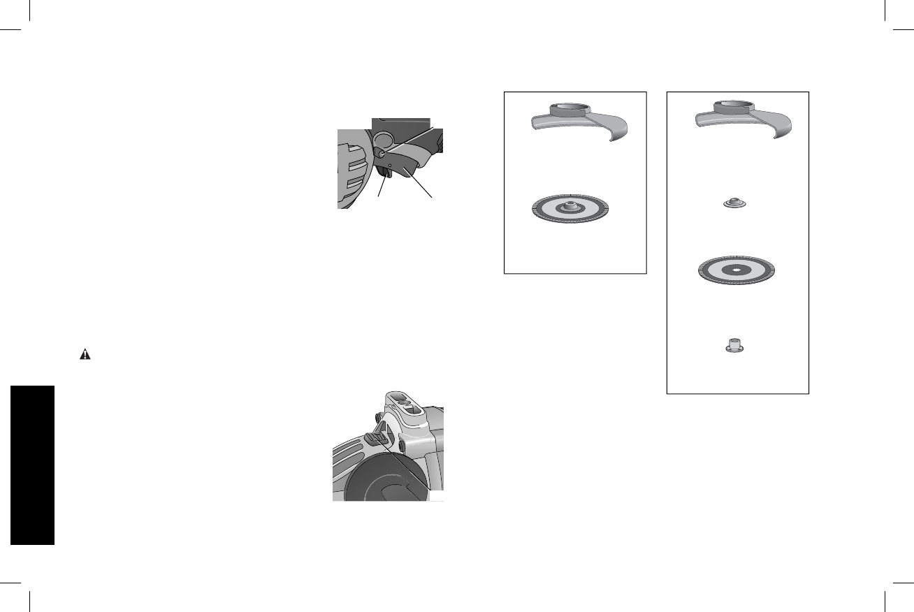
Sanding Flap Discs
Type 27 guard
D284937 7" (180 mm)
D284939 9" (230 mm)
Type 27 guard
D284937 7" (180 mm)
D284939 9" (230 mm)
hubbed sanding flap
disc
non-hubbed sanding
flap disc
clamp nut
22191-00
backing flange
54339-00
NOTE: Wheel size must match guard size; i.e., a new 7" (180mm)
wheel may not be used with a 9" (230 mm) guard. The bottom
surface of wheel must be inside the bend of the guard lip.