


60
English
ASSEMBLY AND ADJUSTMENTS
WARNING: To reduce the risk of injury, turn unit off
and disconnect it from power source before installing and
removing accessories, before adjusting or when making
repairs. An accidental start-up can cause injury.
WARNING: Prior to assembly and adjustment, ALWAYS unplug tool.
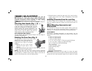
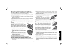
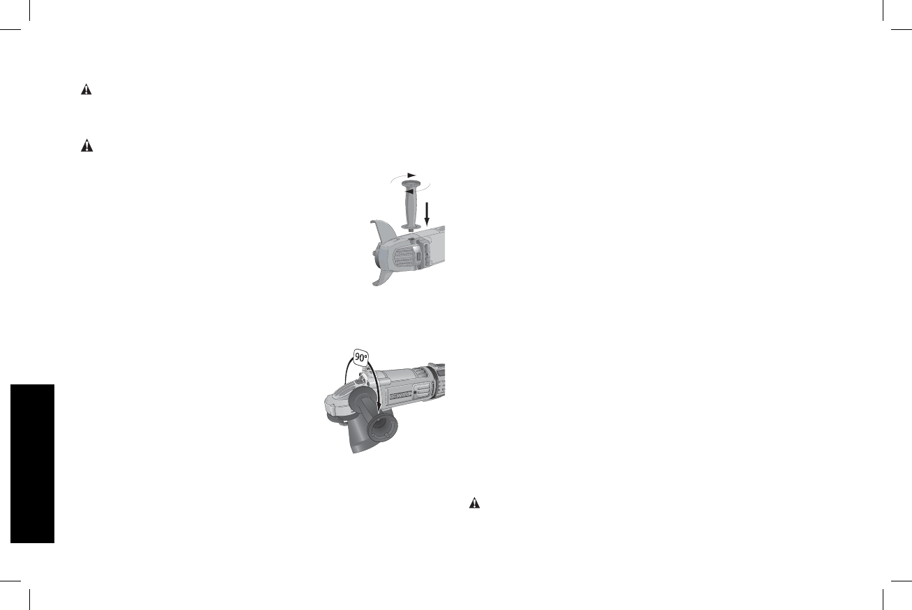
Attaching Side Handle (Fig. 1, 2)
The side handle (H) can be fitted to either side or top
FIG. 2
of the gear case in the threaded holes. The side
positions are designed for optimized balance in
surface finishing and grinding applications. The
side handle must be used at all times to maintain
proper control of the tool. Before using the tool,
check that the handle is tightened se cure ly.
ANTI-VIBRATION SIDE HANDLE
The anti-vibration side handle reduces vibration and user fatigue in
extended use applications.
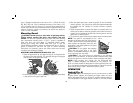
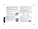
Rotating the Gear Case (Fig. 3)
For applications in which a tool will be
FIG. 3
dedicated for uses in edge grinding and
finishing work, the gear case may be
rotated 90° left or right of its original
position.
1. Remove the four corner screws
attaching the gear case to motor
housing.
2. Without separating the gear case from motor housing, rotate the
gear case head to desired position.
NOTE: If the gear case and motor housing become separated
by more than 1/8" (3.17 mm), the tool must be serviced and
re-assembled by a D
EWALT service center. Failure to have the tool
serviced may cause brush, motor and bearing failure.
3. Reinstall screws to attach the gear case to the motor housing.
Tighten screws to 20 in.-lbs. torque. Overtightening could cause
screws to strip.
Installing Grounded Cord Set and Plug
The above models can be outfitted with a grounded cord set and
retain its compliance approval. Contact your local service center for
installation.
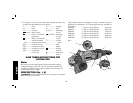
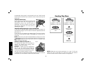
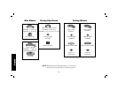
Wheel Mounting Accessories and
Attachments
It is important to choose the correct guards, backing pads and
flanges to use with grinder accessories. Refer to pages 62–64 for
information on choosing the correct wheel mounting accessories.
ATTACHMENTS
Attachments designed specifically for this grinder can be
purchased through D
EWALT dealers and DEWALT Factory Service
centers.
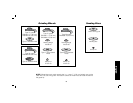
9" (230mm) Type 27 guard
9" (230mm) Type 28 guard
7" (180mm) Type 27 guard
5"–6" (127–152mm) Type 11 Flaring cup guard with flange
4" (101mm) Type 11 Flaring cup guard with flange
Type 11 Flaring cup wheel backing flange
Type 1 Flange set
7" (180mm) Type 1 Guard
Grinding backing flange
Clamp nut
Wheel Wrench
Soft mount spindle protector
WARNING: Accessories must be rated for at least the speed
recom mended on the tool warning label. Wheels and other accessories
running over their rated accessory speed may fly apart and cause