


65
English
Mounting and Using Depressed Center
Grinding Wheels and Sanding Flap Discs
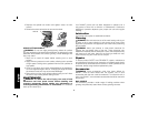
MOUNTING AND REMOVING HUBBED WHEELS
Hubbed wheels install directly on the 5/8"–11 (B3) & M14 (AR, B2,
B2C, BR threaded spindle.
1. Thread the wheel on the spindle by hand, seating the wheel
against the soft mount.
2. Depress the spindle lock button and use a wrench to tighten the
hub of the wheel.
3. Reverse the above procedure to remove the wheel.
CAUTION: Failure to properly seat the wheel against the soft
mount before turning the tool on may result in damage to the tool or
the wheel.
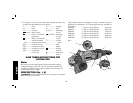
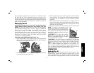
MOUNTING NON-HUBBED WHEELS
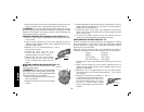
Depressed center Type 27 grinding wheels
FIG. 8
O
E
P
must be used with available accessory flanges.
See the chart on pages 62–64 of this manual
for more information.
1. Install the metal backing flange (O) on
spindle (E) against the soft mount.
2. Place wheel against the backing flange,
centering the wheel on the backing flange
pilot.
3. While depressing the spindle lock button,
thread the clamp nut (P) on spindle,
piloting the raised hub on clamp nut in the
center of grinding wheel.
4. Tighten the clamp nut with a wrench.
5. Reverse the above procedure to remove the wheel.
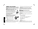
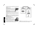
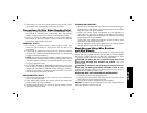
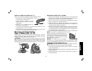
SURFACE GRINDING WITH GRINDING WHEELS (FIG. 9)
1. Allow the tool to reach full speed before touching the tool to the
work surface.
2. Apply minimum pressure to the work surface, allowing the tool
to operate at high speed. Grinding rate is greatest when the tool
operates at high speed.
3. Maintain a 20° to 30° angle between the tool and work surface.
4. Continuously move the tool in a forward
FIG. 9
20˚–30˚
and back motion to avoid creating gouges
in the work surface.
5. Remove the tool from work surface
before turning tool off. Allow the wheel to
stop rotating before laying the tool down.
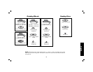
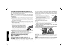
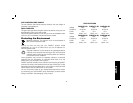
EDGE GRINDING WITH GRINDING WHEELS (FIG. 10)
WARNING: Wheels used for cutting and edge
FIG. 10
grinding may break or kickback if they bend or
twist while the tool is being used to do cut-off
work or deep grinding. To reduce the risk of
serious injury, limit the use of these wheels with a
standard Type 27 guard to shallow cutting and
notching (less than 1/2" [13 mm] in depth). The
open side of the guard must be positioned away
from the operator. For deeper cutting with a Type
1 cut-off wheel, use a closed Type 1 guard. Refer
to pages 62–64 for more information.
1. Allow the tool to reach full speed before touching the tool to the
work surface.
2. Apply minimum pressure to the work surface, allowing the tool
to operate at high speed. Grinding rate is greatest when the tool
operates at high speed.
3. Position yourself so that the open-underside of the wheel is
facing away from you.
4. Once a cut is begun and a notch is established in the workpiece,
do not change the angle of the cut. Changing the angle will cause
the wheel to bend and may cause wheel breakage. Edge grinding
wheels are not designed to withstand side pressures caused by
bending.