


8
English
FIG. 25
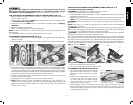
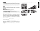
• The saw blade furnished with your new saw is a 10" (254mm) combination blade, used
for crosscutting (across the grain) and ripping (with the grain) through the material. The
center hole to fit on the arbor is 5/8" (16mm) diameter. This blade will produce a good
quality cut for most applications.
• There are many types of blades available to do specific and special jobs such as cross
cut only, rip only, hollow ground, thin plywood, paneling, etc.
• Use only saw blades designed for maximum safe operating speeds of 5,000 RPM or
greater.
• Saw blades should always be kept sharp. It is recommended that you locate a
reputable sharpening service to sharpen your blades when needed.
• Never stack blades on top of one another to store. Place material such as cardboard
between them to keep the blades from coming in contact with one another.
CAUTION: To reduce the risk of injury, abrasive wheels or blades (including diamond)
should not be used on this saw.
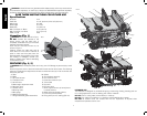
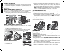
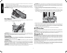
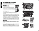
Splitter and Riving Knife Selection (Fig. 26–28)
WARNING: To minimize the risk of kickback and to ensure proper cutting, the splitter and
riving knife must be the proper thickness for the blade used.
The splitter and riving knife supplied with this table saw is the correct size for the blade
supplied with the saw.
If a different blade is used, check the blade body (plate) thickness and the blade kerf (cutting)
width marked on the blade or on the blade packaging. The splitter and riving knife thickness
must be greater than the body thickness and less than the kerf width as shown in Figure 26.
RIVING KNIFE
THICKNESS
KERF WIDTH
(WIDTH OF CUT
MADE BY THE
BLADE)
BODY (OR PLATE)
THICKNESS OF THE
BLADE
FIG. 26
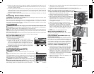
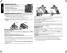
POSITION 2 FENCE ALIGNMENT
(FIG. 22, 23)
1. To align position 2 fence locator pins, ensure position 1 pins have been aligned, refer to
Position 1 Fence Alignment.
2. Loosen the position 2 locator pins, then using the blade wrench holes as a guide for
positioning, align the pins (Fig. 23).
3. Tighten the locator pins (front and rear).
FIG. 23
DD
U
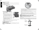
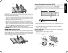
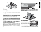
ALIGNING RIVING KNIFE TO BLADE (FIG. 24)
1. Remove the throat plate. Refer to Remove Throat
Plate under Assembly.
2. Raise the blade to full depth of cut and 0° bevel
angle.
3. Locate the three small set screws (PP) adjacent to
the riving knife lock knob (QQ). These screws will
be used to adjust the riving knife position.
4. Lay a straight edge on the table against two blade
tips. The riving knife should not touch the straight
edge. If needed, loosen the two larger lock screws
(RR).
5. Adjust the small set screws (PP) to move the riving
knife according to the position noted in step 5. Lay
the straight edge on the opposite side of the blade
and repeat adjustments as needed.
6. Lightly tighten the two larger lock screws (RR).
7. Place a square flat against the riving knife to verify the riving knife is vertical and in-line with
the blade.
8. If needed, use the set screws to bring the riving knife vertical with the square.
9. Repeat steps 5 and 6 to verify position of riving knife.
10. Fully tighten the two larger lock screws (RR).
Saw Blades (Fig. 25)
WARNING: Riving knives must be matched to saw blade dimensions in order to function
effectively. Refer to Riving Knife Selection.
NOTE: THIS SAW IS INTENDED FOR USE ONLY WITH SAW BLADES 10" (254mm) IN
DIAMETER.
FIG. 24
PP
RR
QQ