


6
English
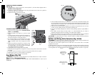
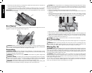
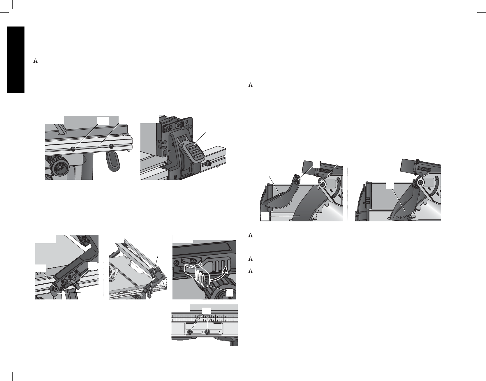
4. Loosen the rip scale indicator screws (GG) and set the rip scale indicator to read zero (0).
Retighten the rip scale indicator screws. The yellow rip scale (top) reads correctly only
when the fence is mounted on the right side of the blade and is in position 1 (for 0 to 24.5"
ripping) [not the 32" rip position]. The white scale (bottom) reads correctly only when the
fence is mounted on the right side of the blade and in position 2 (for 4" to 32.5" ripping).
NOTE: For the DWE7491 the white scale (bottom) reads correctly only when the fence is
mounted on the right side of the blade and in position 2 (for 8" to 28.5" ripping)
A metric scale is available at an additional cost, refer to Accessories for details.
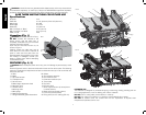
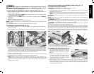
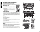
ANTI-KICKBACK ASSEMBLY (FIG. 15, 16)
WARNING: To reduce the risk of serious personal injury, the anti-kickback assembly must
be in place for all possible cuts.
1. Remove the anti-kickback assembly (N) from the storage position. Refer to Storage.
2. Locate the anti-kickback mounting slot (HH) at the top of the splitter (M).
3. Align the stem (II) with the mounting slot. Depress the stem (II) and push down on the
anti-kickback assembly (N) until it snaps and locks into place. NOTE: Pull on the anti-
kickback assembly to ensure it has locked into place.
4. To remove the anti-kickback assembly, depress the stem and pull up and out of the
mounting slot.
With power disconnected, operate the blade tilt and height adjustments through the extremes
of travel and ensure the blade guard assembly clears the blade in all operations and that the
anti-kickback assembly is functioning.
FIG. 16
FIG. 15
N
M
N
HH
II
Bench Mounting
WARNING: Before mounting to a bench or a stand, to reduce the risk of serious
personal injury, turn unit off and disconnect machine from power source before
attempting to move it, change accessories or make any adjustments. An accidental
start-up can cause injury.
CAUTION: To reduce the risk of personal injury, make sure table saw is firmly mounted to
a stable surface or stand provided before use.
CAUTION: Ensure that the surface is stable enough that large pieces of material will not
cause it to tip over during use.
The table saw must be mounted firmly. The mounting surface must have a 15" by 15" (38
x 38cm) opening to allow dust to escape.
Four holes (I) are provided in the tool’s base for mounting. We strongly recommend that these
holes be used to anchor the table saw to your workbench or other stationary rigid frame.
1. Center the saw on a square piece of 1/2" (12.7mm) plywood. The plywood must have a
15" x 15" (38 x 38 cm) opening to allow dust to escape.
2. Mark the positions of the two rear mounting holes (spaced 8-5/8" [220 mm] apart) in the
frame of the saw with a pencil. Then measure forward 19-5/8" (498.5 mm) the two front
holes.
3. Remove the saw and drill 5/16" (7.9 mm) holes in the places you have just marked.
TO REMOVE THE THROAT PLATE
1. Remove the throat plate (Q) by turning the cam lock knob (BB) 1/4 turn counterclockwise
2. Using finger hole (CC) on the plate, pull throat plate up and forward to expose the inside
of the saw. DO NOT operate the saw without the throat plate. If using dado blade, use
proper dado throat plate (sold seperately).
WARNING: To reduce the risk of serious personal injury, the throat plate must be locked in
place at all times.
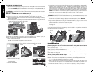
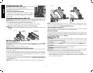
DWE7490 - ASSEMBLING THE RIP FENCE (FIG. 9, 10)
The rip fence can be installed in two positions on the right (position 1 for 0" to 24.5" ripping,
and position 2 for 4" to 28.5" ripping) and one position on the left of your table saw.
1. Align the locator pin (DD) on the fence rail with the fence head slot and align the latch (S)
with the opening (EE).
2. Secure the rip fence by snapping the latches onto the rails as shown in Figure 9. Be sure
to snap both front and rear latches (S) in place.
FIG. 10
FIG. 9
S
EE
DD
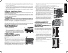
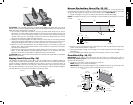
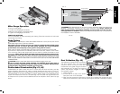
DWE7491 - ASSEMBLING THE RIP FENCE (FIG. 11–13)
The rip fence can be installed in two positions on the right (Position 1 for 0" to 24.5" ripping, and
Position 2 for 8" to 32.5" ripping) and one position on the left of this saw.
1. Unlock the fence latches (S).
2. Holding the fence at an angle, align the locator pins (front and back) (DD) on the fence
rails with the fence head slots (FF) as shown in Figure 11.
3. Slide the head slots onto the pins and rotate the fence down untill it rests on the rails.
4. Lock the fence in place by closing the front and back latches (S) onto the rails.
FIG. 12
FIG. 13
S
FIG. 11
S
E
FF
DD
ADJUSTING THE RIP SCALE (FIG. 12, 14)
1. Unlock the rail lock lever (E).
2. Set the blade at 0° bevel and move the fence in until it
touches the blade.
3. Lock the rail lock lever.
151413 1817 20 21916
76510912 1118
FIG. 14
GG