


4
English
FIG. 2
A
Q
K
E
D
F
S
G
L
T
R
H
C
FIG. 3
P
U
T
S
I
V
B
O
M
N
INTENDED USE
This table saw is designed for professional ripping, crosscutting, mitering, beveling and non
thru-cutting applications, such as dadoing, with various materials.
DO NOT use for cutting metal, cement board, or masonry.
DO NOT use under wet conditions or in presence of flammable liquids or gases.
DO NOT let children come into contact with the tool. Supervision is required when
inexperienced operators use this tool.
WARNING: Use of this tool can generate and/or disperse dust, which may cause serious
and permanent respiratory or other injury. Always use NIOSH/OSHA approved respiratory
protection appropriate for the dust exposure. Direct particles away from face and body.
SAVE THESE INSTRUCTIONS FOR FUTURE USE
Specifi cations
Amperes 15 A
Table Size 21-7/8" (556 mm) X 26-3/8" (669 mm)
Miter Angle 30° L&R
Bevel Angle 0° to 45°L
Blade Size 10" (254mm)
Max. Cut Depth, 0° Bevel 3-1/8" (79mm)
Max. Cut Depth, 45° Bevel 2-1/4" (57mm)
RPM, no load 4800
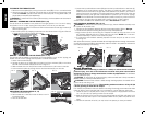
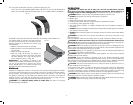
Unpacking (Fig. 1)
WARNING: To reduce the risk of injury,
DO NOT connect the machine to the
power source until the table saw is
completely assembled and you have read
the entire instruction manual.
Open the box and slide the saw out, as
shown in Figure 1.
Carefully unpack the table saw and all
loose items from the carton. Examine all
parts to make sure that parts have not
been damaged during shipping. If any parts
are missing or damaged, contact your
dealer to replace them before attempting
to assemble the tool.
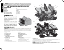
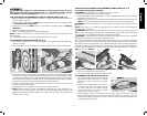
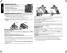
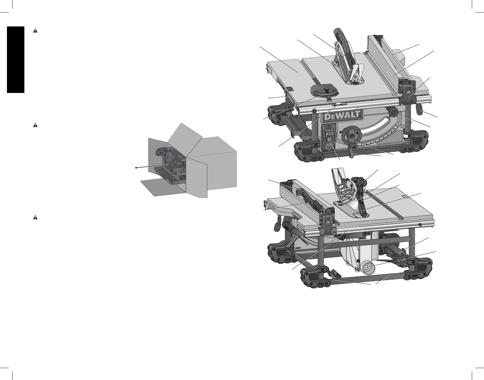
FEATURES (Fig. 2, 3)
WARNING: Never modify the power tool or any part of it. Damage or personal injury could
result.
Examine Figures 2 and 3 to become familiar with the saw and its various parts. The following
sections on assembly and adjustments will refer to these terms and you must know what and
where the parts are.
A. Table
B. Blade
C. Rip scale indicator
D. Fine adjust knob
E. Rail lock lever
F. Blade height adjustment wheel
G. Bevel lock lever
H. ON/OFF switch
I. Mounting holes
J. Miter gauge
K. Blade guard assembly
L. Riving knife/blade guard release lever
M. Splitter
N. Anti-kickback assembly
O. Dust collection port
P. Guard dust collection port
Q. Throat plate
R. Rip fence
S. Rip fence latch
T. Work support/narrrow rip fence (shown
in stored position)
U. Blade wrenches (stored position)
V. Push stick (stored position)
W. Riving knife (non thru sawing) (FIG. 27)
FIG. 1
J