


7
English
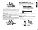
1. Using a 6mm hex wrench, loosen rear pivot bracket fasteners (LL) just enough to allow
the bracket to move side-to-side.
2. Adjust the bracket until the blade is parallel to the miter gauge slot.
3. Tighten the rear pivot bracket fasteners to 110–120 in-lbs (12.5–13.6 Nm).
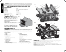
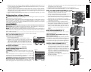
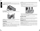
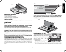
BEVEL STOP AND POINTER ADJUSTMENT (FIG. 19, 20)
1. Raise the blade fully by rotating the blade height
adjustment wheel (F) clockwise until it stops.
2. Unlock the bevel lock lever (G) by pushing it up and to
the right. Loosen the bevel stop screw (NN).
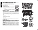
3. Place a square flat against the table top and against the
blade between teeth, as shown in Figure 20. Ensure the
bevel lock lever is in its unlocked, or up, position.
4. Using the bevel lock lever, adjust the bevel angle until it
is flat against the square.
5. Tighten the bevel lock lever by pushing it down.
6. Turn the bevel stop cam (MM) until it firmly contacts the
bearing block. Tighten the bevel stop screw (NN).
7. Check the bevel angle scale. If the pointer does not
read 0°, loosen pointer screw (OO) and move the
pointer so it reads correctly. Retighten the pointer
screw.
8. Repeat at 45°, but do not adjust pointer.
MITER GAUGE ADJUSTMENT (FIG. 2)
To adjust miter gauge (J) loosen knob, set to desired
angle and tighten knob.
FENCE ALIGNMENT ADJUSTMENT (FIG. 2, 21)
(Blade Parallel to Fence)
If you experience fence alignment problems and want
to correct an out of parallel alignment between the
fence and the blade, be sure to check the alignment
of the blade to the miter slot first. After confirming that
those elements are aligned, proceed with alignment of
the blade to the fence using the following procedure:
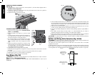
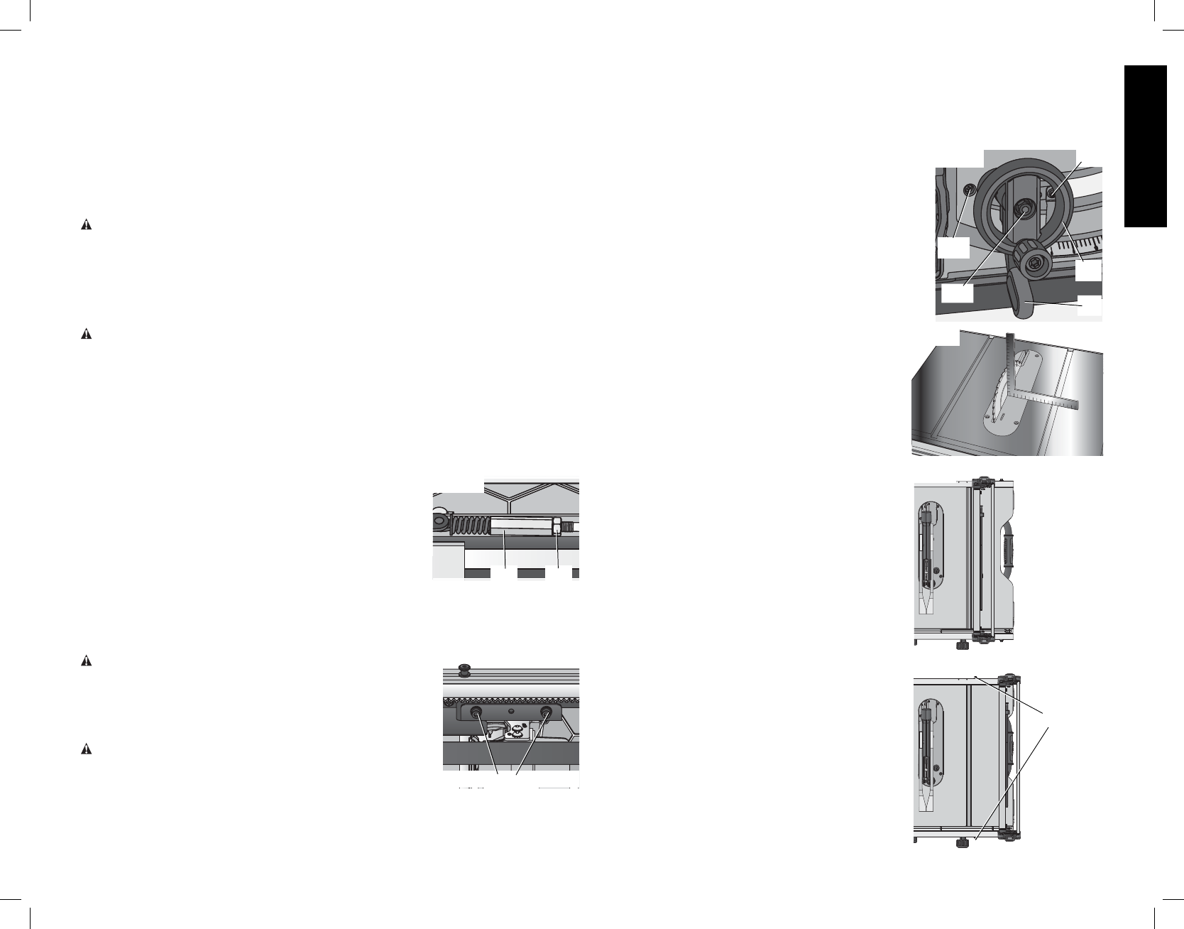
POSITION 1 FENCE ALIGNMENT (FIG. 21)
1. Install the fence in position 1 (Fig. 21) and unlock
the rail lock lever (E). Locate both locator pins (DD)
that support the fence on the front and rear rails.
2. Loosen the rear locator pin screw and adjust the
allignment of the fence in the groove until the
fence face is parallel to the blade. Make sure you
measure from the fence face to the front and back
of the blade to ensure alignment.
3. Tighten the locator pin screw and repeat on the
left side of the blade.
4. Check rip scale pointer adjustment.
FIG. 19
G
OO
F
NN
MM
FIG. 20
FIG. 21
POSITION 1
POSITION 2
FIG. 22
DD
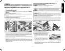
4. Position the saw over the four holes you drilled in the plywood and insert four 1/4"
(6.4mm) machine screws FROM THE BOTTOM. Install washers and 5/16" (7.9 mm) nuts
on the top. Tighten securely.
5. In order to prevent the screw heads from marring the surface to which you clamp the saw,
attach two strips of scrap wood to the bottom of the plywood base. These strips can
be attached with wood screws installed from the top side as long as they don’t protrude
through the bottom of the strip.
6. Use a “C” clamp to secure the plywood base to your workbench whenever you use the
saw.
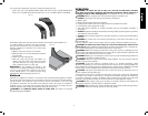
Connecting Saw to Power Source
WARNING: To reduce the risk of injury, before connecting saw to power source, make
sure the switch is in the OFF position.
Be sure your power supply agrees with the name plate marking. AC ONLY means that this
saw will operate on alternating current only. A voltage decrease of 10 percent or more will
cause a loss of power and overheating. All D
EWALT tools are factory tested. If this tool does
not operate, check the power supply.
ADJUSTMENTS
WARNING: To reduce the risk of injury, turn unit off and disconnect machine from
power source before installing and removing accessories, before adjusting or changing set-
ups or when making repairs. An accidental start-up can cause injury.
NOTE: This saw is fully and accurately adjusted at the factory at the time of manufacture. If
readjustment due to shipping and handling or any other reason is required, follow the sections
below to adjust this saw.
Once made, these adjustments should remain accurate. Take a little time now to follow these
directions carefully to maintain the accuracy of which this saw is capable.
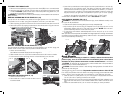
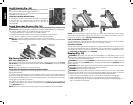
RAIL LOCK ADJUSTMENT (FIG. 2, 17)
(Tightening Fence Clamping System)
1. Lock the rail lock lever (E).
2. On the underside of the saw, loosen the jam nut (JJ).
3. Tighten the hex rod (KK) until the spring on the locking
system is compressed creating the desired tension on the
rail lock lever. Retighten the jam nut against the hex rod.
4. Check that the fence does not move when the lock lever is
engaged. If the fence is still loose, tighten the spring further.
RIP SCALE ADJUSTMENT
See Adjusting the Rip Scale under Assembly.
BLADE ALIGNMENT ADJUSTMENT (FIG. 18)
(Blade Parallel to Miter Slot)
WARNING: Cut Hazard. Check the blade at 0˚ and 45˚ to
make sure blade does not hit the throat plate, causing personal
injury.
If the blade appears to be out of alignment with the miter slot on
the table top, it will require calibration for alignment. To realign the
blade and miter slot, use the following procedure:
WARNING: To reduce the risk of injury, turn unit off and
disconnect machine from power source before installing and
removing accessories, before adjusting or changing set-ups or
when making repairs. An accidental start-up can cause injury.
FIG. 17
KK
JJ
FIG. 18
LL