


5
English
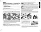
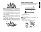
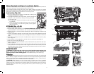
POSITIONING THE BLADE GUARD ASSEMBLY/RIVING KNIFE (FIG. 5, 6)
To position the blade guard assembly:
WARNING: Use the blade guard assembly for all thru-sawing.
1. Raise the saw blade arbor to its maximum height.
2. Install blade guard assembly by pulling the riving knife/guard release lever (L) and inserting
splitter (M) until it bottoms out.
3. Release lever, make sure clamp plates are fully closed and the splitter is clamped securely.
NOTE: Pull on the blade guard assembly/riving knife to ensure it has locked into place.
WARNING: Use the riving knife for non thru-sawing when blade guard assembly cannot
be used.
NOTE: Follow steps 1–3 to install the riving knife (W) in the same manner as the blade guard
assembly, Refer to figure 24.
WARNING: Before connecting the table saw to the power source or operating the saw,
always inspect the blade guard assembly and riving knife for proper alignment and clearance
with saw blade. Check alignment after each change of bevel angle.
WARNING: To reduce the risk of serious personal injury, DO NOT operate saw if riving knife
or blade guard assembly is not securely clamped in place.
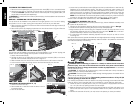
When properly aligned, the blade guard assembly/riving knife will be in line with the blade at
both table top level, and at the top of the blade. Using a straight edge, ensure that the blade
(B) is aligned with the riving knife (W) or the splitter (M). With power disconnected, operate the
blade tilt and height adjustments through the extremes of travel and ensure the blade guard
assembly clears the blade in all operations and that the anti-kickback assembly is functioning.
FIG. 6
M
B
FIG. 7
K
FIG. 5
L
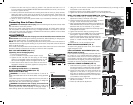
To remove the blade guard assembly/riving knife (FIG. 5, 7)
1. Pull the riving knife/guard release lever (L).
2. Lift up on blade guard assembly(K)/riving knife (W).
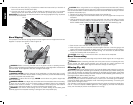
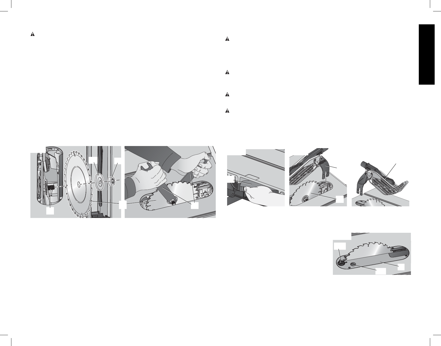
TO ASSEMBLE THE THROAT PLATE (FIG. 8)
1. Align the throat plate (Q) as shown in Figure 8,
FIG. 8
BB
CC
Q
and insert the tabs on the back of the throat
plate into the holes on the back of the table
opening.
2. Rotate cam counterclockwise until the front
of throat plate drops into place. Secure
by rotating cam lock knob (BB) clockwise
1/4 turn (when cam lock is under the table
holding the throat plate in place).
3. The throat plate includes four adjustment screws which raise or lower the throat plate.
When properly adjusted, the front of the throat plate should be flush or slightly below the
surface of the table top and secured in place. The rear of the throat plate should be flush
or slightly above the table top.
ASSEMBLY
WARNING: Shock Hazard. To reduce the risk of serious personal injury, turn unit
off and disconnect machine from power source before attempting to move it, change
accessories or make any adjustments. An accidental start-up can cause injury.
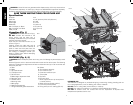
THIS SAW SHOULD BE ASSEMBLED IN THE FOLLOWING ORDER: (FIG, 2, 4)
1. Make sure blade is installed correctly and arbor nut is tight. Use wrenches (U) stored on
the tool. Refer to Figure 3.
2. Install and lock throat plate (Q). (NOTE: Adjust leveling screws before proceeding. Refer
to To Assemble the Throat Plate.)
3. Attach the rip fence (R). (NOTE: Adjust rip scale before proceeding. Refer to Adjusting
Rip Scale.)
4. Position the blade guard assembly.
5. Attach anti-kickback assembly to the guard assembly.
NOTE: To attach this table saw to a stand, please follow the instructions included with the
stand assembly.
Tools needed for assembly include the wrenches included with this saw.
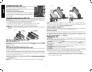
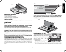
ATTACHING/REPLACING THE BLADE (FIG. 2, 4)
1. Raise the saw blade arbor to its maximum height by turning the blade height adjustment
wheel (F) clockwise.
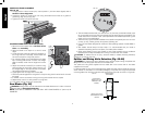
2. Remove the arbor nut (X) and flange (AA) from the saw arbor by turning counterclockwise.
AA
X
FIG. 4
Y
U
B
3. Place the saw blade on to the spindle (Y) making sure the teeth of the blade (B) point down
at the front of the table. Assemble the flange and arbor nut to the spindle and tighten arbor
nut (X) as far as possible by hand, making sure that the saw blade is against the inner washer
and the flange (AA) is against the blade. Ensure the largest diameter of the flange is against
the blade. Ensure the spindle and flange are free from dust and debris.
4. To keep the spindle from rotating when tightening the arbor nut, use the open end of the
wrench (U) to secure the spindle.
5. Using the arbor wrench, tighten the arbor nut (X) by turning it clockwise.
6. NOTE: Different types of blades make different kerfs (width of cuts). Therefore, it is
necessary to check adjustment of rip scale when changing blades. Replacement blade
MUST not exceed the thickness stated on the riving knife. The riving knife provided with
the saw is 2.2mm thick.