


9
11.02
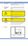
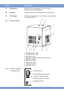
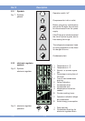
The cooling air for the refrigerant condenser will be
sucked in at the front panel (fig. 5/3). This area must be
kept free and not be obstructed.
If necessary, sufficient cooling air supply must be pro-
vided by additional wall openings .
The cooling air outlet is positioned at the top of the unit
(fig. 5/8). Ensure a free air outlet and do not obstruct the
outlet of the cooling air.
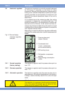
If the CA-dryer is connected to an exhaust trunk, an ad-
ditional fan must be installed to compensate the pres-
sure drop. The controlling of the fan must be provided
through the CA-dryer.
The connection must be executed acc. to marking at the
CA-dryer (fig. 5/1+2).
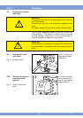
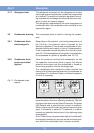
For service purposes the installation of a bypass line is
recommended (additional equipment).
Attention!
Before mounting the CA-dryer, welding residual, rust or
other pollution must be removed from the pipelines to
be connected. If pollution cannot be excluded, proper
filter system must be installed
The compressed air pipes must be installed stress-free.
Expansion joints are recommended in case of vibrations
and pulsations.
The CA-dryers are completely equipped and wired. They
merely have to be connected to a power supply. The
CA-dryers are to be protected by slow-blow fuses as
defined in the wiring diagram.
Operation voltage: acc. to name plate or wiring dia-
gram resp.
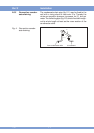
Attention!
Due to transportation reasons the power connection
cable with installed cable gland is located inside the cas-
ing of the CA-dryer.
After removal of the side wall (fig. 5/9) the cable gland
is mounted and fastened in the corresponding pas-
sage (fig. 5/6) of the casing.
Part 2 Installation
2.3.1 Version air cooled
2.4 Compressed air con-
nection
2.5 Electric connection
!