


11
ENGLISH
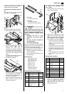
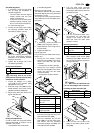
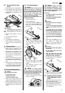
Saw blade alignment
1. If necessary, crank the saw blade
fully up using the handwheel to
check the alignment.
− The saw blade must be aligned
exactly parallel with the side
edges of the table top.
− It must not touch the table insert
extrusion (neither in the 90° posi-
tion nor in the 45° bevel position).
To correct the alignment:
2. Loosen the six flange nuts holding
the fastening brackets under the
saw table by approx. one turn.
3. Move the fastening brackets, with
the motor unit/chipcase assembly
attached to it, as required, until the
alignment is correct.
4. Tighten the six flange nuts of the
two fastening brackets.
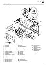
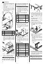
Riving knife installation
A
Danger!
The riving knife is one of the
safety devices and has to be correctly
installed for a safe operation:
1. Loosen the hexagon nut (= Keps
nut) (116) at the pressure plate
(117) approx. two turns.
2. Slide the riving knife (118) as illus-
trated between riving knife carrier
(119) and pressure plate(117).
3. Adjust riving knife (see below) and
tighten the Keps nut.
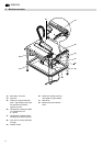
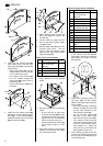
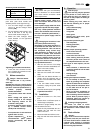
Riving knife adjustment.
In order to match the riving knife exactly
with the saw blade, its position can be
adjusted in two planes:
− in the distance to the saw blade;
− in its lateral alignment.
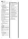
Distance to the saw blade:
The distance between the saw blade's
peripheral edge and the riving knife shall
be between 3...8 mm.
The riving knife must project at least the
same distance over the saw table as the
saw blade.
1. If necessary, loosen the Keps nut
(120) on the riving knife one turn.
2. Adjust distance of the riving knife to
the saw blade.
3. Tighten the Keps nut.
Lateral alignment:
riving knife and saw blade must be per-
fectly in line.
• Turning the four hexagon socket
head cap screws (121) on the motor
carrier unit below the saw table
clockwise
= riving knife is moved to the right.
• Turning the four hexagon socket
head cap screws (121) on the motor
carrier unit below the saw table
counter-clockwise
= riving knife is moved to the left.
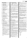
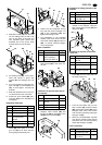
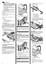
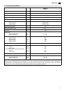
Table insert extrusion installation
1. Put the countersunk screw (122)
from the top through the hole in the
table insert extrusion (123).
2. From the underside, put the cam
plate (124) on the flat head screw
and secure with the prevailing
torque-type hexagon nut (125) – the
cam plate remains rotatable.
3. Turn flat head screw clockwise
(viewed from top) until it stops, and
place table insert extrusion flush into
the table top's slot.
4. Turn the countersunk screw coun-
ter-clockwise: the cam plate will
engage in the recess of the saw
table and locks the table insert
extrusion in place.
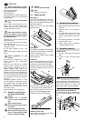
Mounting the switch
• Attach the switch plate with two
each hexagon head screws (126)
and flange nuts (127) to the left front
leg. The switch buttons must point to
the right-hand side.
A
Caution!
Make sure the cable does not
run over sharp edges and is not bent.
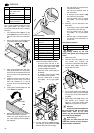
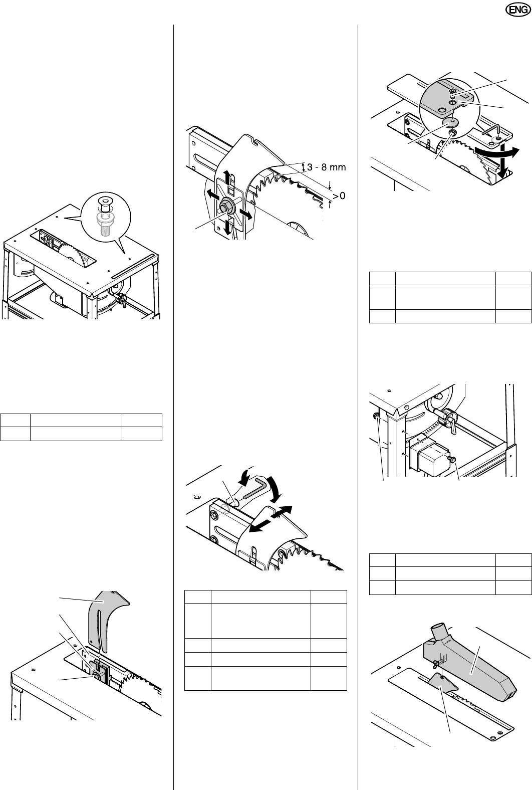
Installing the dust collection gear
1. Install blade guard (128) on the riv-
ing knife (129).
2. Push one end of the suction hose
(131) on the blade guard's suction
port (130).
Item Description Qty.
118
Riving knife
1
117
116
119
118
Item Description Qty.
122
Hex. socket counter-
sunk head screw
M6 x 16
1
123
Table insert
1
124
Cam plate 25 mm
1
125
Hexagon nut, prevailing
torque type, M6
1
120
121
Item Description Qty.
126
Hexagon head screw
M8 x 16
2
127
Flange nut M8
2
Item Description Qty.
128
Blade guard
1
131
Suction hose
1
122
123
124
125
126127
128
129