


7
ENGLISH
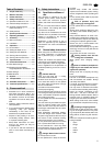
In order to prevent the set blade tilt to
change during cutting, its position is
locked with the lock lever (50).
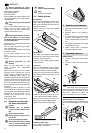
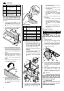
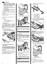
Handwheel for setting the depth of
cut
The depth of cut can be adjusted by
turning the handwheel (51).
Fence
The saw is equipped with two fences:
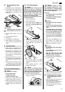
• Mitre fence (for cross/mitre cuts):
For use as mitre fence the short
fence extrusion (52) must be
installed. The mitre fence is
mounted on a guide bar, fastened to
the left-hand side of the saw table.
The plastic nose of the fence extru-
sion must point towards the saw
blade.
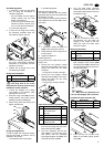
For mitre cuts, the fence extrusion is
adjustable to 45° maximum.
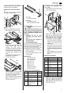
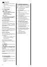
• Rip fence (for ripping):
For use as rip fence the long fence
extrusion (53) must be installed. It is
mounted on the guide extrusion at
the front of the saw table.
After loosening the two knurled nuts
(54), the fence extrusion can be
removed and shifted:
Wide edge:
− for cutting thick stock
Small edge:
− for cutting thin stock;
− when the saw blade is tilted.
A
Danger!
Modifications of the saw or the
use of parts not tested and approved
by the equipment manufacturer can
lead to unforeseen damage during
operation!
− Assemble the saw in strict
accordance with these instruc-
tions.
− Use only the parts supplied as
standard delivery.
− Do not change any parts.
Only if you follow the instructions exactly
does the saw conform to the safety regu-
lations and can be safely operated.
If you also observe the following notes,
the assembly will cause no problems:
• Read the instructions for each step
before executing it.
• Lay out the parts required for each
assembly step.
Required tools
− Hex. wrench 4 mm
− Hex. wrench 5 mm
− Hex. wrench 6 mm
− Wrench 10 mm
− Wrench 13 mm
− Wrench 17 mm
− Wrench 19 mm
− Ring spanner 46 mm
− Philips screwdriver
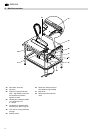
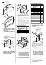
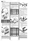
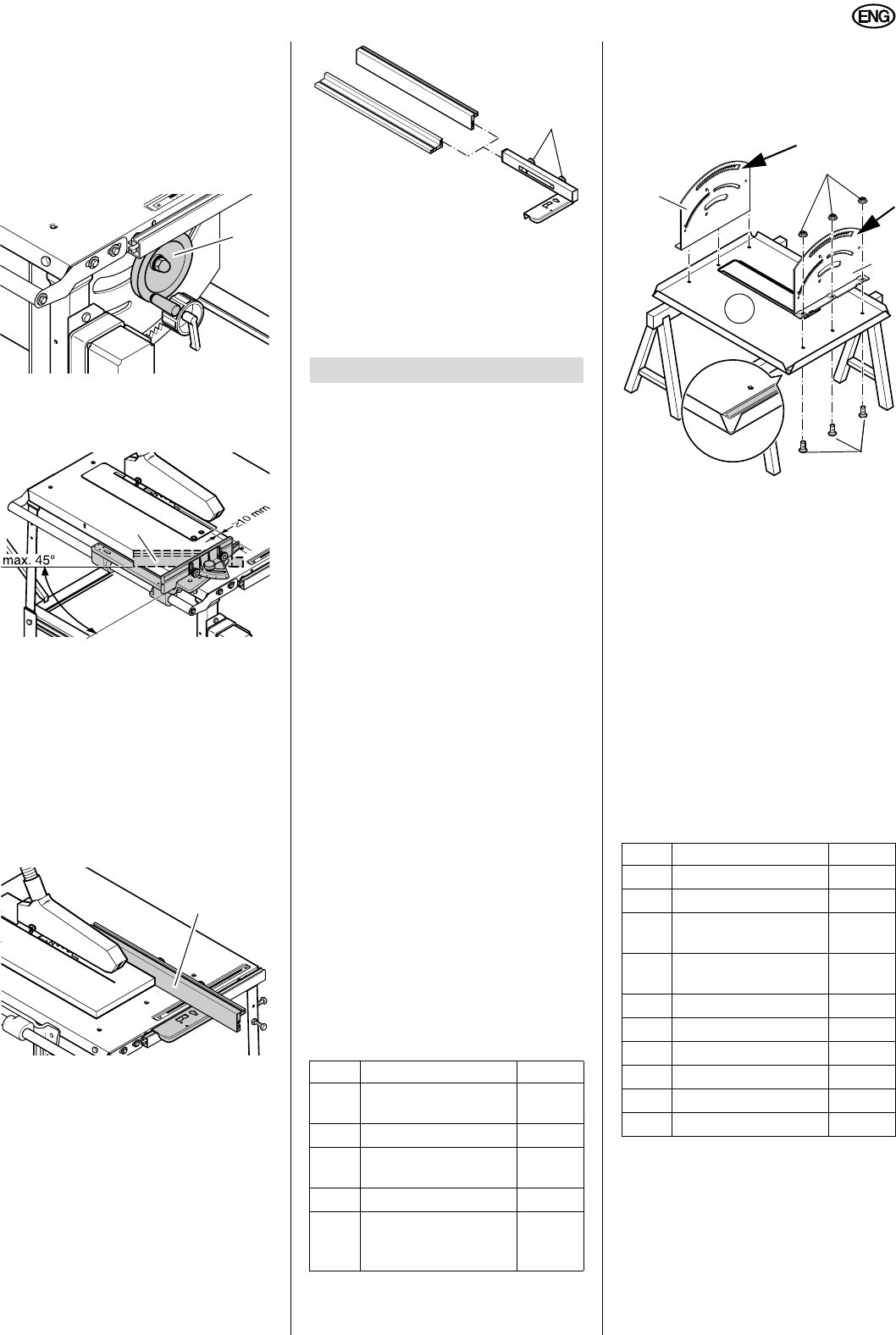
Chipcase guide panel installation
The chipcase guide panels (55) and (57)
are installed on the underside of the
table top (58).
1. Place table top with the folds facing
up on a sturdy support.
2. Attach front chipcase guide panel
(57) and rear chipcase guide panel
(55) using three each countersunk
screws (59) and flange nuts (56) to
the underside of the table top(58):
− The front of the saw is where the
recess for the rip fence scale is
located in the table top (see
image detail).
− The square ends of the curved
oblong holes (arrows) must face
the edge of the table top which is
closer to the opening for the saw
blade.
− The folded edges of the chipcase
guide panels must point out-
wards.
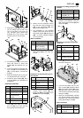
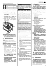
Bearing plate installation
1. Attach two each cam plate (61)
(hole not in centre) with hexagon
head screw (62) and hexagon nut
(60) fingertight to the inside of each
chipcase guide panel.
51
52
53
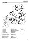
7. Assembly
Item Description Qty.
55
Chipcase guide
panel, rear
1
56
Flange nut M8
6
57
Chipcase guide
panel, front
1
58
Table top
1
59
Hex. socket counter-
sunk head screw
M8 x 25
6
54
Item Description Qty.
60
Hexagon nut M6
4
61
Cam plate
4
62
Hexagon head screw
M6 x 16
4
63
Hexagon head screw
M8 x 20
4
64
Guide roller
4
66
Bearing plate, rear
1
67
Flange nut M8
4
68
Bearing plate, front
1
70
Indicator
1
71
Angle scale
1
56
57
55
58
59