


18
3.4 PREAMPLIFIER TROUBLESHOOTING. To deter-
mine if the preamplifier is operable, proceed as follows:
1. Remove the sensor from process.
2. Remove the cover from the body by grasping the
body and rotating the cover 1/4 turn in the count-
er-clockwise direction.
3. When the cover breaks loose from the body, pull
straight out on the cover to expose the com-
ponents attached to the body and disconnect the
BNC connector from the preamplifier, leaving the
cable connected. Inspect the internal pre amplifier
area for signs of moisture or corrosion; moisture
can short out the preamplifier. Dry all parts thor-
oughly before testing.
4. Short the center pin of the BNC on the preamp-lifi-
er to the outside of the BNC connector.
5. The meter indication should be approximately
center scale (7 pH).
6. If the meter indication is not as specified in Step 5,
proceed to the transmitter instruction manual for
further troubleshooting. If the transmitter is opera-
ble with the preamplifier bypassed, then the pre-
amplifier is defective.
7. Unplug the preamplifier from the body.
8. Plug a new preamplifier into the body.
9. Plug the BNC connector of the glass electrode into
the preamplifier.
10. Make sure all O-rings are clean, lubricated and in place.
11. Plug the cable connector into the preamplifier, making
sure the cable is towards the center of the body.
12. Install the cover on the body so that the threads
engage.
13. Rotate the cover until the triangle on the body
aligns with (or falls within) the adjacent mark on
the cover.
CAUTION
DO NOT use a pipe wrench on the body or
cover. Severe damage could result.
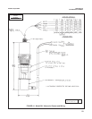
14. Install the sensor as described in Section 2.0.
MODEL 381pH/ORP SECTION 3.0
MAINTENANCE
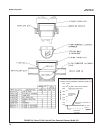
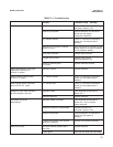
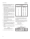
3.5 T Automatic Temperature Compensator. The temper-
ature compensator element is temp erature sensitive and
can be checked with an ohmmeter. Resistance increases
with temperature.
The 3K element will read 3000 ohms ±1% at 25°C (77°F)
and a Pt-100 will read 110 ohms. Resistance varies with tem-
perature for a 3K and Pt-100 element and can be determined
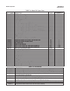
according to Table 3-2 or the following formula:
R
T
=R
o
[l+R
1
(T-20)]
Where R
T
= Resistance
T = Temperature in °C
Refer to Table 3-3 for R
o
and R
1
values
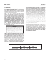
TABLE 3-3
R
o
and R
1
VALUES FOR TEMPERATURE
COMPENSATION ELEMENTS
TABLE 3-2
TEMPERATURE vs RESISTANCE OF AUTO
T.C. ELEMENT
Temperature °C Resistance
(Ohms) ± 1%
3K PT-100
0 2670 100.0
10 2802 103.8
20 2934 107.7
25 3000 109.6
30 3066 111.5
40 3198 115.4
50 3330 119.2
60 3462 123.1
70 3594 126.9
80 3726 130.8
90 3858 134.6
100 3990 138.5
Temperature
Compensation Element
R
o
R
1
3K 2934 .0045
PT-100 107.7 .00385