


5
MODEL 381pH/ORP SECTION 2.0
INSTALLATION
SECTION 2.0
INSTALLATION
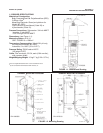
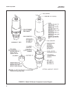
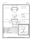
2.1 INSTALLATION. Prepare the sensor for instal lation
as follows (see Figure 2-1):
1. Remove the cover from the body by grasping the
body and rotating the cover 1/4 turn counter-
clockwise.
2. When the cover breaks loose from the body, pull
the cover straight out.
3. Lubricate the seals of the glass electrode with O-
ring lubricant, Rosemount Analytical P/N
2001928, and install the glass electrode in the
body. Tighten the electrode nut by hand. DO NOT
use tools.
CAUTION
Do not get lubricant on amber tip of glass
electrode. It will disrupt the electrical circuit
path.
4. Make sure the double junction electrode is thread-
ed tightly.
5. Plug the preamplifier (or remote connector) onto
the T.C. and reference electrode pins.
6. Connect the BNC connector from the glass elec-
trode to the preamplifier.
7. Install the body O-rings. Make sure they are clean,
and not twisted. Make sure the covers mating sur-
faces faces are clean.
NOTE
Both body O-rings must be installed and
lubricated to ensure a water tight seal.
Failure to seal the body properly will result
in water damage, in insertion applications.
8. Lubricate the body O-rings with O-ring lubricant,
P/N 2001928.
9. Plug the cable connector to the preamplifier, mak-
ing sure the cable is toward the center of the body.
10. Install the cover on the body so that the threads
will engage.
11. Rotate the cover until the triangle on the body
aligns with (or falls within) the adjacent mark on
the cover.
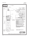
IMPORTANT!
12. While holding the sensor in an up side down posi-
tion (see Figure 2-1), remove the 1/4 inch plug
from the electrode tip end of the sensor.
13. Install the liquid junction in place of the 1/4 inch
plug, using Teflon tape on the liquid junction
threads.
CAUTION
DO NOT use pipe joint compound or pipe
dope on the threads of the liquid junction.
The electrical circuit will be disrupted if the
liquid junction is contaminated.
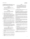
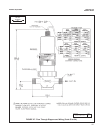
2.2 SUBMERSION INSTALLATION (Code 02). To
install the sensor in process proceed as follows (see
Figure 2-2):
1. Wrap Teflon tape on 3/4 inch MNPT threads of
cover and on standpipe threads. Seal must be
water tight. Cable gland is not waterproof. Do not
allow water to accumulate in the stand pipe.
CAUTION
Do not use a pipe wrench on the plastic
parts. Severe damage could result.
2. Attach a 3/14 inch coupling to the sensor.
3. Attach electrode shroud to 2 inch MNPT.
4. Feed cable through the rigid standpipe.
5. Attach the rigid standpipe to 1 inch coupling.
CAUTION
Rigid stand pipe must be water-tight; cable
seal is not waterproof.
6. Tighten all fittings and secure the standpipe to
minimize sensor movement. Use flexible conduit
at the top of the rigid standpipe to permit removal
of the sensor for periodic maintenance.
7. Refer to Section 2.6 and wire the sensor to the
transmitter as described.