21
MODEL 381pH/ORP SECTION 4.0
ULTRASONIC CLEANER
SECTION 4.0
ULTRASONIC CLEANER
4.1 ULTRASONIC CLEANER (P/N 22727-00). This
accessory provides an ultrasonic cleaner and mount-
ing hardware for either continuous or inter-mittent
cleaning of the measuring electrode and liquid junction
on the Model 381. The information in the following
paragraph is supplemental to the information in
Sections 1.0 thru 3.0.
4.2 SPECIFICATIONS. The ultrasonic cleaner oper-
ates on either 115 Vac or 230 Vac, 50/60 Hz. The mode
is jumper selectable within the generator enclosure.
The generator is shipped in the 115 Vac configuration.
4.3 INSTALLATION. The ultrasonic generator is
shipped with special cushioning material. Before open-
ing the container or removing any packing material, all
items should be inspected for any possible shipping
damage. If any damage is found, the carrier should be
notified. Check the generator enclosure for damage to
the finish; loosen the door clamps and inspect the cir-
cuit board and components. If there is apparent dam-
age, contact the carrier for instructions. The packing
container and cushioning material should be retained
should it ever become necessary to return the genera-
tor to the factory. Install the ultrasonic cleaner as fol-
lows:
1. Mechanical Installation. Although the generator is
designed to be located in a process environ-ment,
corrosive atmospheres and excessive vibration
should be avoided if possible. The ultrasonic
transducer is shipped loose along with mounting
hardware and mounting instructions. Check to
make certain all connections are secure. Refer to
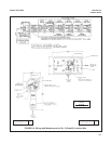
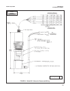
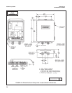
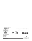
Figure 4-1 and 4-2 for mounting dimensions and
select a convenient location for the generator.
2. Electrical Installation. An external line switch
should be installed to disconnect power from the
generator for maintenance or periods of non-use.
Apply input power (refer to Figure 4-2) as follows:
Ground to TB1-8, hot to TB1-6, and neutral to TB1-7.
CAUTION
Make sure the 115/230 jumpers on the
transformer are in the proper position for
the supply voltage being used. The gener-
ator will be seriously damaged if 230 Vac is
supplied with the jumpers in the 115 Vac
position.
The power output is approximately 1400 volts at 0.002
amp, at a frequency of 40 to 45 kHz. The transducer is
supplied with 20 feet of interconnecting cable in a
polypropylene protective sheath. Output connections
are made at TB1-4 for R.F. (+) and TB1-2 for RF(-).
Make sure the AC power line ground is properly con-
nected to the generator’s input terminals.
CAUTION
Do not run any ultrasonic cleaner power,
wiring input or output, in the same conduit
as the signal wiring from the sensor.
4.4 OPERATION. Submerge the sensor into sample
and start the sensor as instructed in Section 2.0. After
measuring system is in operation, apply AC power to
the ultrasonic cleaner. Over a period of time (usually
several days), gradually increase the gain until the
power setting is sufficient to keep the electrodes free of
process buildup.
CAUTION
Increase gain slowly and apply only the
necessary amount of power. Excessive
power may damage the electrode. Once
initial start-up is complete, further adjust-
ment or calibration is not normally required
unless there are drastic changes in the
composition of the process sample.


