


MODEL 381 pH/ORP TABLE OF CONTENTS
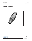
MODEL 381 pH/ORP SENSOR
LIST OF FIGURES
Figure No. Title Page
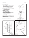
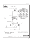
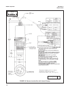
1-1 Dimensional Drawing ........................................................................................ 3
1-2 Mounting Drawing ............................................................................................. 3
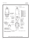
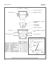
2-1 Model 381 Sensor Component Locator Diagram.............................................. 6
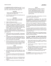
2-2 Submersion Installation Diagram ...................................................................... 8
2-3 Insertion Installation Diagram............................................................................ 8
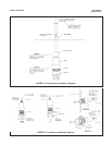
2-4 Flow Through Installation Diagram (Code 03 or 04) ......................................... 9
2-5 Installation Details Low Flow Conditions Model 381 (Code 03-04)................... 9
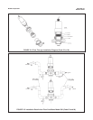
2-6 Retro-Fit Kit and Code-04 Flow Powered Cleaner, Model 381 ......................... 10
2-7 Flow Through Diagram and Wiring (Code 03 or 04) ......................................... 11
2-8 Remote Junction Box with Internal Preamp...................................................... 12
2-9 Wiring with Weatherproof or Div. 2 (Code 2) Junction Box .............................. 13
4-1 Model 381 Ultrasonic Cleaner and Wiring......................................................... 23
4-2 Dimensional and Component Locator Ultrasonic Generator............................. 24
ii
About This Document
This manual contains instructions for installation and operation of the Model 381
pH/ORP Sensor.
The following list provides notes concerning all revisions of this document.
Rev. Level
Date Notes
A 6/94-1/00 This is the initial release of the product manual. The manual
has been reformatted to reflect the Emerson documentation
style and updated to reflect any changes in the product offering.
B 5/02 Updated multiple drawings throughout manual.
C 3/05 Updates
D 10/07 Updated page 3 code 00 insertion is no longer available.