


6 • MRLDS I&O Manual 026-1307 Rev 1 11-30-07
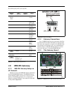
4.2.3 Address Settings
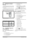
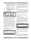
4.2.4 Refrigerant Jumper Settings
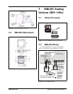
The jumper settings for refrigerant types are located on
the label inside the MRLDS sensor cover (shown in Fig-
ure 1-1). Set the jumpers according to how they are indi-
cated on the label.
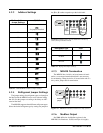
The MRLDS supports three different refrigerant types.
Select the desired refrigerant type by setting one jumper to
the J2 or J1 sockets respective per the inside label.
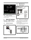
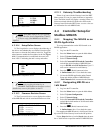
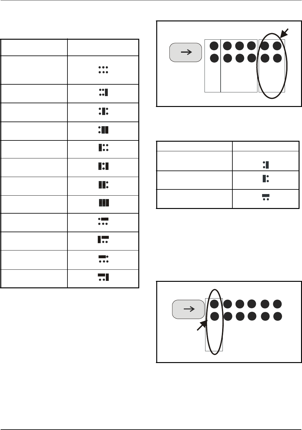
4.2.5 MRLDS Termination
The MRLDS has a built-in, on-board means of termi-
nation, so an external termination block is not necessary
for terminating. When the device is located at the end of a
daisy chain, jumper JP6 for termination.
4.2.6 Modbus Output
See Table 4-3 below for Modbus registers in the
MRLDS Unit. Baud rate: 19,200; each byte is 8 (eight)
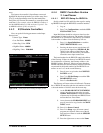
Modbus Address
Jumper Settings
J5|J4|J3
100
No jumpers installed
101
102
103
104
105
106
107
108
109
110
111
Table 4-1
- MRLDS Modbus Address Jumper Settings
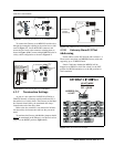
Figure 4-4 - Modbus Jumper Layout (Inside Lower Portion of
Cover) Enlarged To Show Detail
Refrigerant Type J2|J1
R-22
R-404A
R-134A
Table 4-2
- Refrigerant Jumper Settings
Figure 4-5 - MRLDS Termination (Inside Lower Left of Cover)
J6
J5 J4 J3
J2 J1
refrigerant
type
jumpers
network
address
jumpers
term
jumper
J6
J1
J6
J5 J4 J3
J2 J1
Termination
jumper
J6
J1