


MRLDS Gateway MRLDS Modbus Version (809-101x) • 9
controller’s user manual.
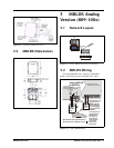
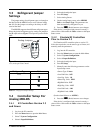
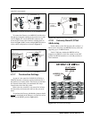
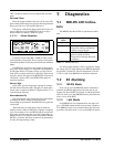
To connect the Gateway to an MRLDS, feed the wires
through the rectangular opening in the sensor base as indi-
cated in Figure 1-1. Locate the RS485 connector and
secure the wire leads to the connector orienting them as
shown in Figure 4-10. Connect multiple MRLDS units in
a daisy-chain configuration as shown in Figure 4-1.
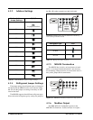
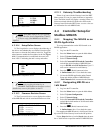
4.3.7 Termination Settings
As part of a site controller’s RS485 I/O (COM A or
COM D) Network, a Gateway must be terminated if it is
the end device of a daisy chain. The Gateway on the Mod-
bus Network should always be terminated and always
located at the end of the daisy chain.
Refer to the site controller’s user manual for informa-
tion about daisy chain networks and how they are termi-
nated.
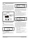
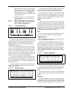
To terminate the Gateway (the Modbus jumpers should
always
be terminated on the Gateway), set the receiver bus
jumpers to the RIGHT position (Figure 4-11).
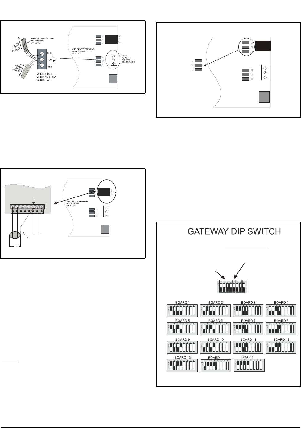
4.3.8 Gateway Board I/O Net
Addressing
Set the address on the I/O Network with switches 1-4.
There can be more than one MRLDS Gateway with each
supporting up to 12 MRLDS units.
Switch 5 indicates whether the MRLDS will be
mapped as an IRLDS or 16AI. Set switch 5 to the OFF
position for IRLDS emulation or to the ON position for
16AI emulation.
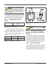
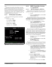
Figure 4-9
- Connecting the Gateway to the E2 RS485 Network
Figure 4-10 - Connecting the Gateway to MODBUS
GATEWAY BOARD
-485
+485
0v
To MRLDS
MODBUS
A
B
R
S
4
8
5
+
R
S
4
8
5
-
A
C
N
2
4
V
A
C
MRLDS - INSIDE LOWER
PORTION OF BASE
GATEWAY BOARD
+485
-485
0v
+485
-485
0v
E
A
R
T
H
G
N
D
Shield
drain/ground
wir
e
Shield drain
/
ground
wire
MODBUS
NETWORK
Figure 4-11 -MRLDS Gateway Termination
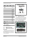
Figure 4-12 - Network Layout Example
RS485
I/O NET
(TO CPC
CONTROLLER
)
RS485 I/O NET
TERM JUMPERS
TERMINATION
(ALWAYS
TERMINATE)
14
15
ADDRESS ON
I/O NET
I/O NET MODE
ON = 16AI
OFF = IRLDS