


8 • MRLDS I&O Manual 026-1307 Rev 1 11-30-07
The Gateway Board communicates with the MRLDS
via the Modbus network, which is connected to the Gate-
way’s “Receiver Bus” network terminal. The Gateway
communicates with the E2 via the RS485 I/O Network.
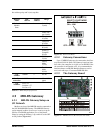
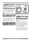
4.3.4 Powering the Gateway
Board
The Gateway board requires 24VAC power from a
Class 2 center-tapped transformer. CPC supplies several
sizes of center-tapped transformers for powering multiple
16AIs, 8ROs, and other RS485 peripheral boards.
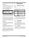
Figure 4-8 shows how to connect the 56VA and 80VA
transformers to the Gateway power connector.
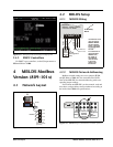
4.3.5 Connecting the Gateway
Board to the Einstein or REFLECS
Network
Each E2, Einstein, or REFLECS site controller that
will communicate with one or more MRLDS units must
have a Gateway Board installed on its RS485 I/O Net-
work. For Einstein controllers, this means the Gateway
will be installed on the RS485 I/O Network; for RMCC,
BEC, BCU, and other REFLECS products, the Gateway
will be installed on the COM A or COM D network.
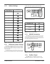
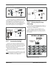
4.3.6 Wire Connections
Using shielded three-conductor network cable (Belden
#8641 or equivalent), connect the RS485 I/O Network
wire to the three-terminal connector on the Gateway board
as shown in Figure 4-9. For further information about
how RS485 networks are configured, refer to your site
CAUTION: Before installing the Gateway
board, verify the jumper JP7 (located near the
top center of the board) is set to the “NOR-
MAL” position (not the “TEST” position). Operating
the Gateway with the jumper in “TEST” position may
cause board damage.
Input Voltage 24VAC, Class 2, Center-Tapped
50/60Hz
Power 5VA
Table 4-4
- Gateway Power Requirements
Three-Board Six-Board
P/N
640-0056 640-0080
Power Rating
56 VA 80 VA
Table 4-5 - Power Ratings for CPC Transformers
Figure 4-8 - Pinout for the 56VA (640-0056) and 80VA (640-
0080) Transformers
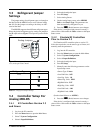
CAUTION: The MRLDS unit requires a sepa-
rate Class 2, 24VAC, 10VA power supply.