


MRLDS Dimensions MRLDS Analog Version (809-100x) • 3
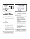
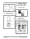
2.2 MRLDS Dimensions
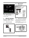
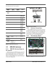
3 MRLDS Analog
Version (809-100x)
3.1 Network Layout
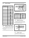
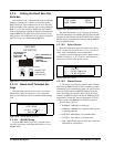
3.2 MRLDS Wiring
For analog MRLDS units, connect to a MultiFlex
board via the analog input (use Belden 8761 cable).
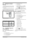
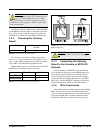
Figure 2-2
- Attaching and Removing Cover
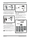
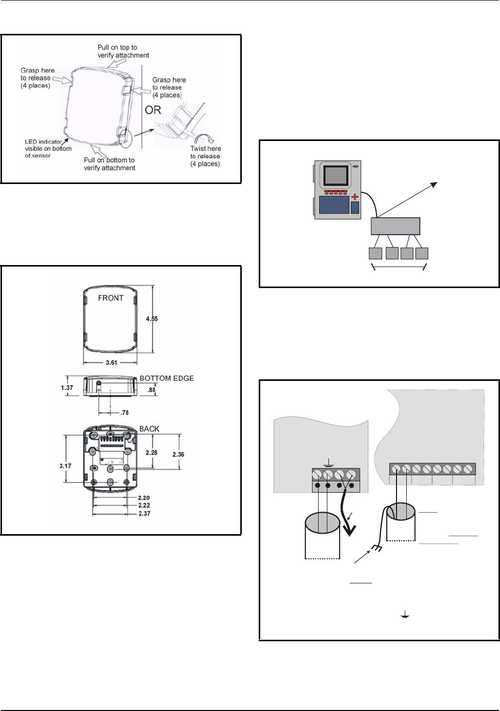
Figure 2-3 - MRLDS Mounting Dimensions
Figure 3-1 - Analog MRLDS Network Layout Example
Figure 3-2 - Analog MRLDS Wiring
E2
MRLD
S
U
nit
s
I/O Net
MultiFlex Board
T
o
O
t
h
e
r
I
/
O
N
e
t
D
e
v
i
c
e
s
ANALOG MRLDS -
INSIDE LOWER PORTION
OF BASE
MULTIFLEX BOARD -
LOWER RIGHT CORNER
INPUT 13
INPUT 14
INPUT 15
INPUT 16
12
34
5
6
7
8
0V
SIG
0V
SIG
SIG SIG
0V 0V
A
C
N
2
4
V
A
C
G
A
S
(
+
)
O
U
T
(
V
)
TO 24VAC, 10VA
CLASS 2 POWER
SUPPLY
Analog MRLDS
to MultiFlex
A
transformer must
be shared
between MRLDS
and the MultiFlex
board. A
must
be used.
If a transformer is
shared between
MRLDS units,
the “ACN” of
each MRLDS
must be wired
to the same
phase of the
t
r
a
n
s
f
o
rm
e
r.
never
separate
transformer
S
I
G
0V
G
r
o
u
n
d
O
U
T
(
V
)
G
r
o
u
n
d
EARTH SHIELD
NEAR THE MULTIFLEX
BOARD. CONNECT
THE SHIELD TO THE 0V INPUT
ON THE MULTIFLEX BOARD.
DO NOT
Wire MultiFlex SIG to MRLDS OUT(V).
Wire MultiFlex 0V to MRLDS Ground ( ).
BELDEN
8761
BELDEN
8761