2 • MRLDS I&O Manual 026-1307 Rev 1 11-30-07
2 Choosing a
Mounting Location
Proper location of the refrigerant sensor is necessary to
ensure accurate measurement of representative air sam-
ples.
Mount the sensor:
• Indoors, inside a room area where air circulates
freely.
• On a flat, interior surface.
• Approximately 12-18 inches (30-45 cm) from
the floor.
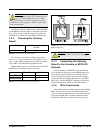
Do not
mount the sensor:
• On surfaces in unheated areas (less than
0°C),
unless using a model with a de-icer.
• Near heat sources, such as appliances, direct
sunlight, or concealed pipes or chimneys.
• On walls subject to excessive vibration.
• In the direct path of an exhaust fan. Excessive
air movement will disperse gas before it can be
detected. If mounting in the path of excessive
airflow cannot be avoided, it will be necessary
to turn OFF air circulation for 1/4 to 1/2 hour,
4-6 times a day.
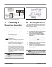
2.1 Mounting The Sensor
The refrigeration monitor comprises two basic parts:
the base and the cover. The cover incorporates the circuit
board with the sensing elements.
1. Fasten the base to a junction box or other support.
The base has a number of openings to allow for
mounting to various junction boxes.
2. Feed the power and signal wires through the rect-
angular opening in the base (Figure 1-1).
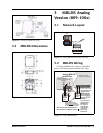
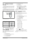
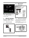
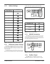
3. Connect the wires to the terminal connector
located in the base, as indicated in Figure 4-2
and Figure 3-2.
4. The Modbus MRLDS must be connected to earth
ground. Connect earth ground to the MRLDS
ground terminal labeled . Connect to earth
ground with 14 AWG wire that is less than 6
inches.
5. Align the two side tabs of the cover with the base
and snap the cover onto the base.
6. Verify the cover is securely attached to the base
by pulling on the top and bottom of the cover as
shown in Figure 2-2.
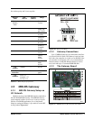
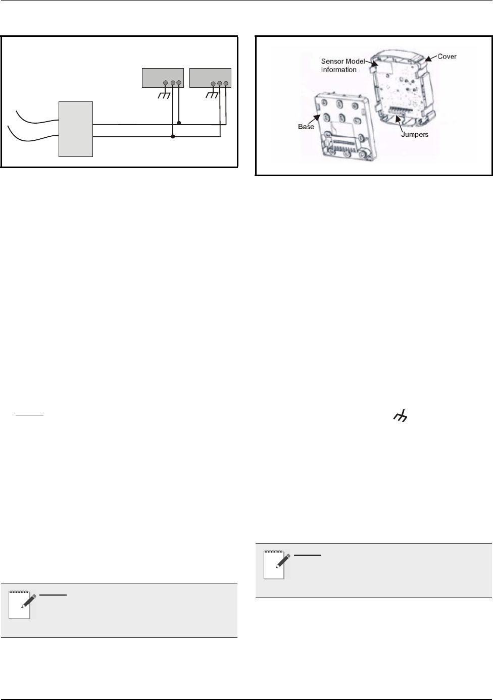
Figure 1-2
- Powering Multiple MRLDS Units
NOTE: For example, if mounted inside a motor
room, exhaust fans must be shut off during the
intervals that air samples will be tested for
refrigerant levels.
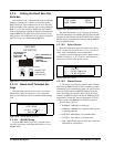
120VAC
24VAC
ACN
T
r
a
n
s
f
o
r
m
e
r
MRLDS I
MRLDS II
I
f
a trans
f
ormer is
shared between MRLDS
units, the “ACN” of each
MRLDS must be
wired to the same phase
of the transformer.
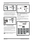
Figure 2-1 - Sensor Base And Cover
NOTE: To remove the cover, grasp it along the
recesses and pull it away from the base (Figure
2-2). Alternatively, place a screwdriver into the
slots indicated in Figure 2-2 and twist.


