8
English
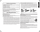
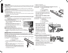
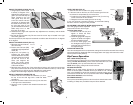
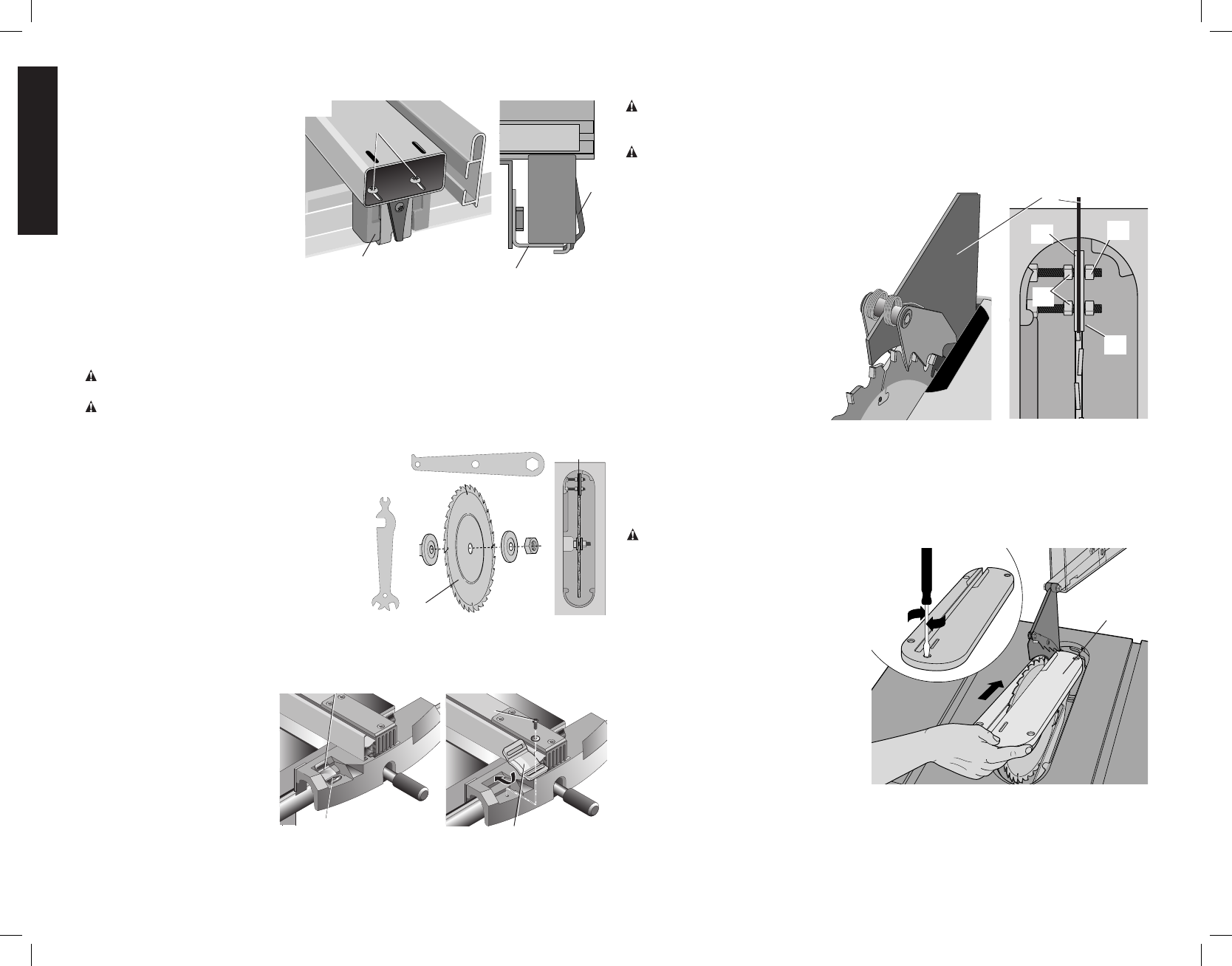
ADJUSTING THE REAR FENCE GLIDE (FIG. 13)
1. Slide the rip fence (G) back
FIG.13
MM
LL
NN
A
and forth to check if it slides
freely over the rails.
2. Lock the rip fence in place
using the rail locking lever (I).
If there is excessive up/down
movement in the rear of the fence
when locking, the rear fence
bracket (LL) needs adjustment.
To adjust:
1. Loosen the screws (MM).
2. Set the retaining clip (NN) so
that it slightly pushes on the rear rail (A).
3. Tighten the screws.
4. Ensure the fence still slides smoothly. If it does not, the retaining clip (NN) is pushing on
the rear rail (A) too strongly.
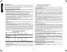
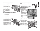
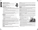
TO INSTALL THE SAW BLADE (FIG.14)
WARNING: Use ONLY 10" (254 mm) diameter blades with 5/8" (16 mm) arbor holes,
rated at 3600rpm or higher.
WARNING: To reduce the risk of injury. Wear gloves when handling saw blades.
1. Set the blade arbor highest position
SPINDLE
LOCK
WRENCH
BLADE WRENCH
FIG. 14
OO
PP
QQ
D
using the blade height adjustment
wheel (M).
2. Remove the nut (OO) and outer clamp
washer (PP)
3. Place the blade (D) onto the arbor with
the teeth pointing towards the front of
the saw.
4. Remount the outer clamp washer (PP)
and nut (OO) as shown. Make sure
that the saw blade is piloted on the
outer clamp washer hub (QQ).
5 Use the spindle lock wrench and blade
wrench to tighten the nut.
NOTE: If the nut fall into the interior of the saw, carefully remove it though the dust port.
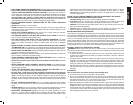
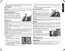
ADJUST THE FENCE SCALE INDICATOR (FIG. 15).
1. Slide the fence until it just
FIG. 15
RR
U
U
RR
touches the blade.
2. Loosen the fence indicator
screw (RR) and slide it until
the hairline aligns with the “0”
line on the scale.
3. Tighten the screw.
4. If the low profile fence face
accessory or a wider home-
made fence face is used
which is out of the adjust-
ment range of the pointer, the
pointer (U) can be removed completely, turned 180 degrees, re-installed, and aligned
with the “0” line.
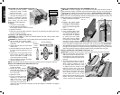
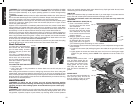
INSTALL THE GUARD AND SPLITTER ASSEMBLY (FIG. 16)
CAUTION: To prevent snagging of the workpiece, the table insert should be flush or
slightly below the surface of the table top and secured in place. The rear of the throat plate
should be flush or slightly above the table top. Refer to Install and Adjust Throat Plate.
CAUTION: When installing the throat plate, always make certain to hold on to the blade
guard. The insert will automatically release the holding action on the splitter and lower the
blade guard when it is installed in the table opening.
1. Raise the blade to its highest
TT
TT
C
UU
FIG. 16
SS
point.
2. Loosen the outer guard
retaining nuts (SS) enough so
the splitter (C) will fit between
the two guard retaining plates
(TT).
3. Install the splitter (C).
4. Using a straight edge, check
to ensure the splitter is prop-
erly aligned with the blade. If
not, the position is adjusted
by moving the inner guard
clamp nuts (UU) to change
the location the splitter. Make
sure there is some clearance
between the splitter and the blade and the blade spins freely. If the splitter is tilted rela-
tive to the blade, the splitter plate can be bent until it lines up correctly. IMPORTANT:
THE GUARD SHOULD BE IN PLACE FOR ALL POSSIBLE CUTS. When making non-
through cuts, the guard can be easily removed by slightly loosening the outer guard nuts
(SS). The guard can easily be replaced without having to readjust the inner nuts.
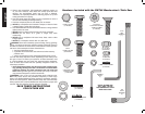
INSTALL AND ADJUST THE THROAT PLATE (FIG. 17)
CAUTION: To reduce the risk of injury. The throat plate must be in place at all times.
1. Align the throat plate (VV) as shown
FIG. 17
VV
and insert the tabs on the back of the
throat plate into the holes at the back
of the table and lower the plate into its
opening.
2. The throat plate includes four adjust-
ment screws which raise or lower it.
When properly adjusted, the front
of the throat plate should be flush
or slightly below the surface of the
table top, and the rear of the throat
plate should be flush or slightly above
the table top. The center front screw,
when turned clockwise, will engage
a cam under the front lip of the
table, locking the throat plate in place.
Rotate the screw counterclockwise
1/2 turn to remove the throat plate.


