9
English
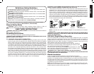
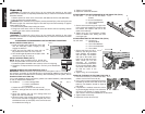
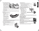
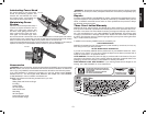
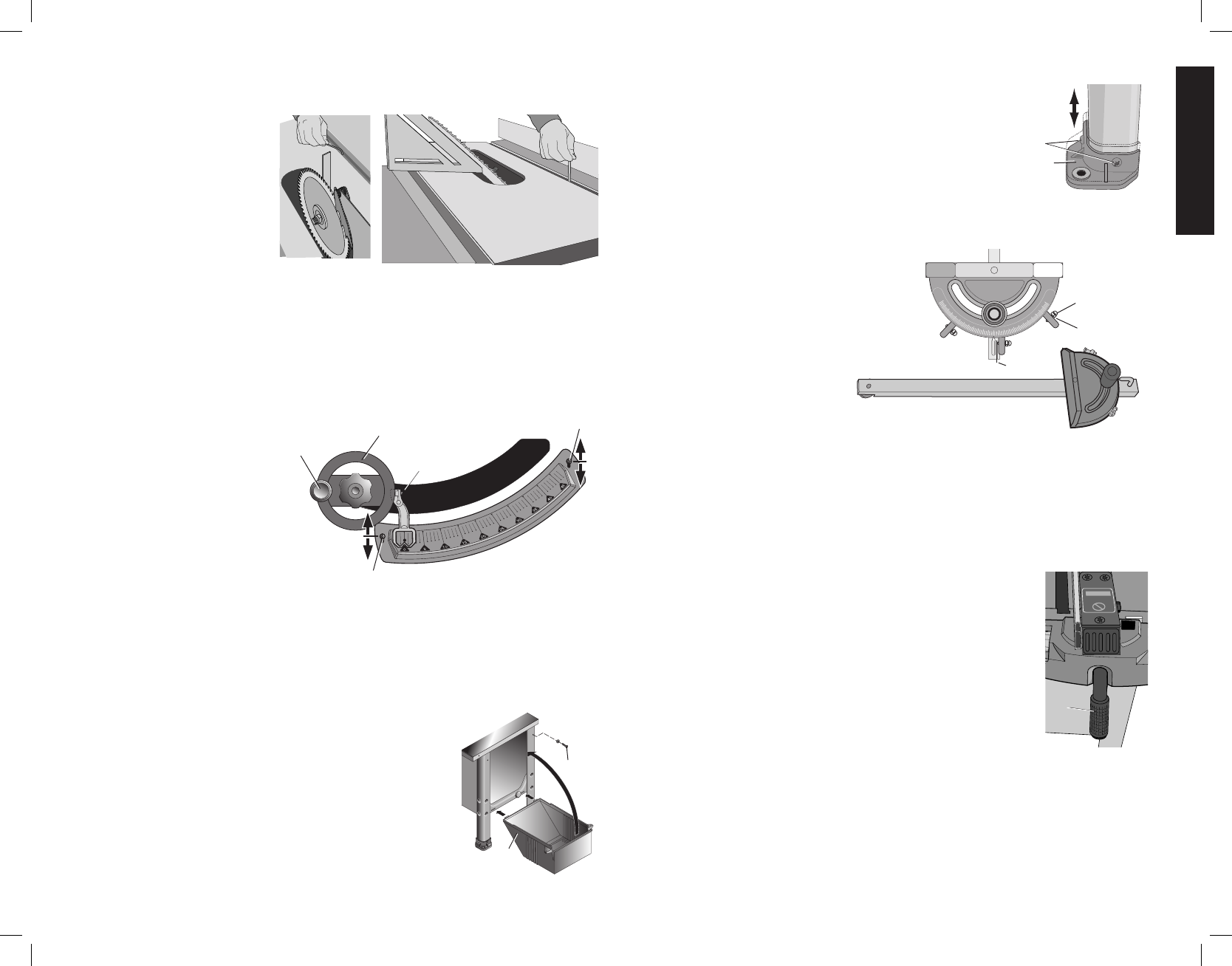
ADJUST THE BEVEL STOPS (FIG. 18)
1. Using a square, set the blade
FIG. 18
to exactly “0” degrees. If the
blade stops beveling before it
gets to 0, loosen the stop set
screw (located in the left
miter guide slot) with the
5 mm hex wrench and then
proceed to “0” degrees. With
the blade set at 0, slowly turn
the zero stop screw in until
you feel resistance. Bevel the
blade away from 0 a little
then back to the stop.
2. Remeasure the angle and repeat the stop adjustment as necessary until the blade
stops at 0 degrees.
3. Set the 45 stop the same way. The set screw for the 45° stop is located in the right
hand miter guide slot.
For some special cuts, the stops can be backed out and the saw will bevel from –2 degrees
to 47 degrees.
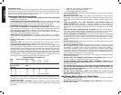
ADJUST THE BEVEL SCALE (FIG. 19)
1. Bevel the saw until it hits the
FIG. 19
BB
M
WW
XX
XX
zero bevel stop.
2. Remove the lock knob (BB)
and blade height adjustment
wheel (M).
3. Adjust the red pointer by
loosening the screw (WW)
where it attaches to its shaft,
move the pointer until it lines
up with the 0 line on the
scale, and retighten the
screw. The pointer should
be positioned just barely off
of the scale surface.
4. Bevel the saw to the 45º stop. If the pointer doesn’t point to 45º, loosen the two screws
(XX) which hold the scale to the saw front panel and slide the scale up or down until
the pointer lines up with the 45 line. Retighten the scale screws.
5. Replace the blade height adjustment wheel and lock knob.
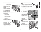
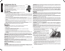
INSTALL THE MOTOR COVER (FIG. 20)
1. Remove the two cover screws and washers (YY) from
FIG. 20
YY
J
the top of the two side legs with a small flat blade
screwdriver.
2. Snap the two bottom tabs of the cover (J) into the slots
in the right lower crossmember.
3. Place the cover in position and reinstall the screws and
washers.
LEVEL THE SAW (FIG. 21)
1. Place the saw in the location it is going to be used.
2. If the saw rocks on the floor, the foot not touching the floor can
FIG. 21
ZZ
L
be lowered to compensate for the uneven floor.
a. Loosen the two screws (ZZ) that hold the foot (L) to the leg.
Let the foot fall to the floor surface.
b. Retighten the screws holding the foot to the leg.
If your saw will have a permanent location, we recommend bolting
the feet to the floor using the holes provided.
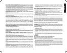
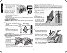
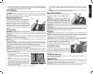
ADJUSTMENT AND USE OF MITER GAUGE (FIG. 22)
Your miter gauge features adjustable
30
30
45
60
75
75
90
60
45
FIG. 22
A1
A2
A3
stops at 90° and 45° left and right.
To adjust these stops:
a. Loosen the lock nuts (A1) and
tighten or loosen the three
adjusting screws (A2).
b. Check the gauge with a square
against the blade and tighten
the three adjusting screws.
c. To set the miter gauge past
the 45 degree stops, flip up the
stop plate (A3) and continue to
the required angle.
CLEAN THE TABLE TOP
Your saw was shipped with a rust preventive coating which should be removed. Clean the top
with mineral spirits or denatured alcohol and apply paste wax. Apply and remove soon after-
ward to prevent a sticky build-up.
Rip Fence Operation
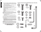
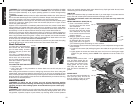
RAIL LOCK LEVER (FIG. 23)
The rail lock lever (I) locks the fence in place preventing movement during
FIG. 23
I
cutting. To lock the rail lever, push it down and toward the rear of the
saw. To unlock, pull it up and toward the front of the saw.
NOTE: When ripping, always lock the rail lock lever.
RIP SCALE POINTER
NOTE: The rip scale pointer will need to be readjusted whenever a
thicker or thinner blade is installed. Should you decide to use a thicker
face, or the D
EWALT low fence face acces sory, the scale pointer may be
removed and turned 180° to line up with the scale. Refer to Adjust the
Fence Scale Indicator under Assembly.
RIP FENCE CAPACITY
The rip fence will slide beyond the end of the rails in either direction with-
out falling off. Stops are provided to keep the fence attached.


