


7
English
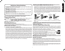
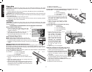
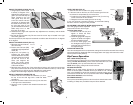
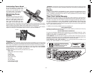
ASSEMBLE THE FENCE BEAM TO THE FENCE HEAD
FIG. 10
G
H
JJ
HH
(FIG. 10).
1. Remove the three flat head screws (HH) securing the
cover plate (JJ) to the fence beam with the T50 Torx
wrench.
2. Turn the rip fence (G) upside down. Slide the fence
beam (H) into the rip fence as shown.
3. Flip the fence beam over and install the cover plate
and three screws. Tighten snug, do not overtighten.
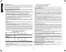
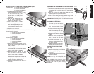
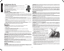
ADJUSTING FENCE TO TABLE TOP (FIG. 11)
IMPORTANT: Check alignment of beam and fence face
before each cutting session.
ALIGNING THE RIP FENCE
1. Place the fence face (F) on the
HH
I
KK
W
FIG. 11
F
Q
front rail (Q) and rear rail (A)
close to the miter slot (W) at
the right-hand side of the
table.
2. Loosen the three locking knobs
(KK). Allow the fence face to
rest on the table top, then tight-
en the locking knobs (KK).
3. Slightly loosen the three screws
(HH).
4. Slide the fence and adjust the
beam angle until the fence
face is in line with the miter
slot (W).
5. Lock the fence beam (H) in
place by pushing the rail lock-
ing lever (I) down.
6. Tighten the locking knobs (KK),
starting with the rearmost two.
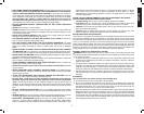
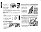
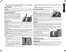
ADJUSTING THE FENCE FACE
(FIG. 12)
1. Loosen the locking knobs (KK).
2. Set the fence face (F) so it clears the
FIG.12
KK
F
B
table top (B) by approx. 1/16"
(1.6 mm).
3. If desired, adjust the fence face for-
ward or backward.
4. Tighten the locking knobs (KK).
NOTE: For very thin workpieces, the
fence face can be set so it rests on the
table top. Make sure to set the fence
face so it clears the table top by approxi-
mately. 1/16" (1.6 mm) before moving
the fence.
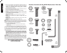
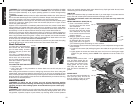
ATTACH THE LEFT & RIGHT SIDE SUPPORT TABLES (FIG. 8)
You will need: 6 – 10 x 25 mm Hex Head Bolts
6 – 10 mm Flat Washers
6 – 10 mm Lock Washers
1. Install the three bolts, flat washers
FIG. 8
V
FF
B
and lock washers in the holes in
the side of the table top (B) as
shown. Keep a 1/4" (6.4 mm)
gap between the table top and
bolt heads.
2. Slide the side support table (V)
on the bolts, fitting into the
notches (FF). Do tighten nuts.
3. Use the fence face as a guide
to flush the support table to the
main table edge and snug the
front bolt. Repeat this process
for the rear bolt. Tighten the cen-
ter bolt.
4. Repeat on the other side.
ATTACH FRONT AND REAR RAILS TO SUPPORT TABLES (FIG. 9)
You will need for front rail:
2 – 10 x 30 mm Flat Head Screws
2 – 10 mm Flat Washers
2 – 10 mm Lock Washers
2 – 10 mm Nuts
You will need for rear rail:
2 – 10 x 25 mm Hex Head Bolts
2 – 10 mm Flat Washers
2 – 10 mm Lock Washers
2 – 10 mm Nuts
1. Align front rail brackets (CC) with the side
FIG. 9
CC
GG
support table (V) and tighten bracket nuts
(GG) to the rail.
2. Attach the support table to the outer front
rail brackets with the screws, flat washers,
lockwashers and nuts. Keep the washers
and nut on the inside of the table.
3. Attach the support table to the outer
rear rails with the bolts, flat washers,
lockwashers and nuts, Keep the washers
and nut on the inside of the table.
4. Using the fence face as a straight edge
make sure the support table is level with
or slightly below the table top. Adjust if
needed and tighten all fasteners.
5. Repeat this procedure for the other sup-
port table.