


10
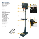
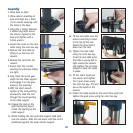
Assembly
1. Place base on floor.
2. Place column assembly on
base and align the 4 holes
in the column assembly with
the holes in the base.
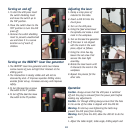
3. Using the 4 10mm diameter
x 46mm long bolts secure
the column support to the
base and tighten with a
16mm wrench.
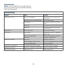
4. Loosen the screw on the rack
collar using the 4mm hex key.
5. Remove the rack collar by
lifting it up and over the
column.
6. Remove the rack from the
column.
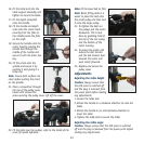
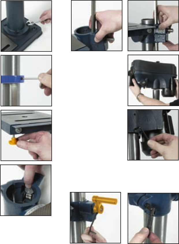
7. Ensure that the 4 knobs
securing the extension tables
are tight.
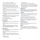
8. Fully insert the worm gear
shaft into the table support
and engage it on the gear
wheel in the assembly.
9. With the short smooth
section of the rack pointing
downwards, slide the rack
through the round opening
in the table support.
10. Engage the rack on the
gear mechanism found
inside the opening of the
table support.
11. Whilst holding the rack and table support slide both
over the column. Slide the rack down until the rack is
positioned against the lower column support.
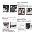
12. Fit the rack collar over the
column and bring it down
to the top of the rack.
Ensure the bevel side is
down over the rack.
13. Tighten the rack collar
using the 4mm hex key.
To let the rack slide when
the table is swung left or
right around the column
only tighten the set screw
enough to keep the collar
in place.
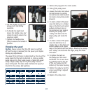
14. Fit the motor head over
the column and tighten
the 2 grub screws using
the 4mm hex key. This will
secure the head on the
column.
15. Attach the table handle to the worm drive shaft and
tighten the grub screw using the 4mm hex key.