


11
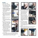
16. Fit the table lock into the
table support assembly and
tighten to secure the table.
17. Fit the depth scale/lock
onto the handle.
18. Fit the handle and depth
scale onto the motor head
ensuring that the flats on
the handle locate the flats
on the shaft.
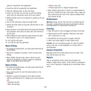
19. Secure the handle onto the
motor head by placing the
handle bolt through the
middle of the handle and
secure it with the 6mm hex
key.
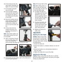
20. Fit the chuck onto the
spindle and secure it by
pushing it and giving it a
sharp tap.
Note. Ensure both surfaces are
clean before putting the chuck
on the spindle.
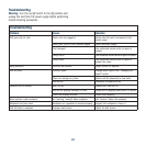
21. Place a screwdriver through
the top of the pulley cover,
loosen and remove the
screw securing the pulley cover. Lift off the cover.
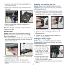
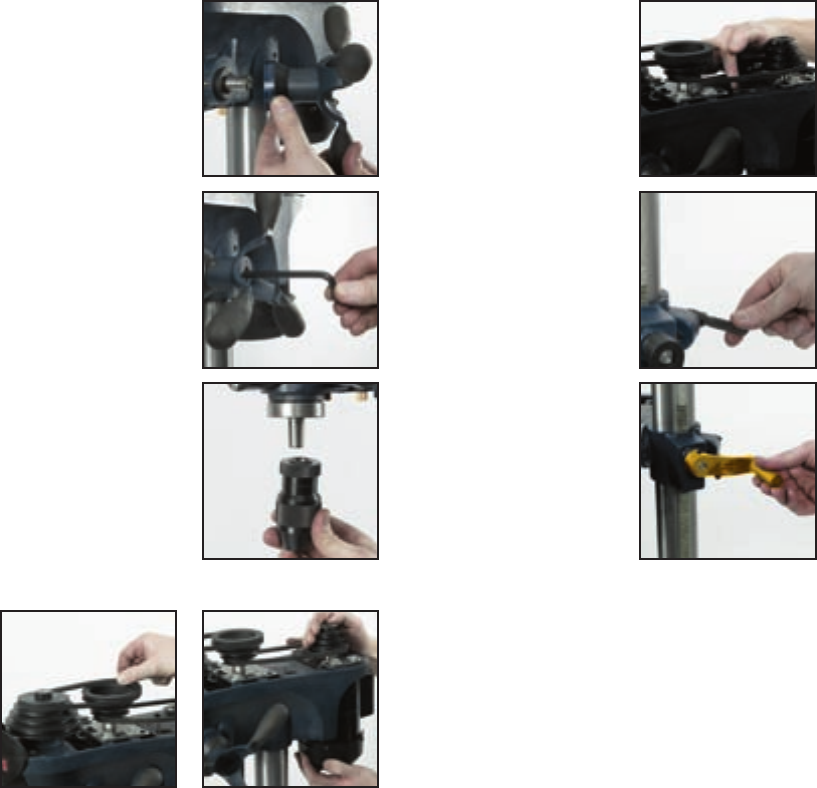
22. Fit the belts over the pulleys, refer to the inside of the
cover for speed reference.
Note. Fit the lower belt on first.
Note. When fitting belts it is
easier to place the belt onto
the small pulley and then turn
it onto the larger pulley.
23. To tighten the belts on
the pulleys pull the motor
backwards. This is best
done by grabbing hold of
the top of the rear pulley
and the bottom of the
motor housing.
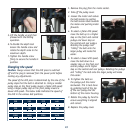
24. To loosen the motor and
reduce the belt tension
pull the belt tension lever
towards the motor and
push motor forwards.
25. Replace and secure the
pulley cover.
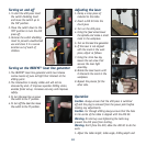
Adjustments
Adjusting the table height
Caution. Always ensure that
the drill press is switched off
and the plug is removed from
the power point before making
any adjustments.
1. Loosen the table lock.
2. Rotate the handle in a clockwise direction to raise the
table.
3. Rotate the handle in an anti-clockwise direction to
lower the table.
4. Tighten the table lock to secure the table.
Adjusting the table angle
Caution. Always ensure that the drill press is switched
off and the plug is removed from the power point before
making any adjustments.