Pump Repair
20 309977H
Pump Repair
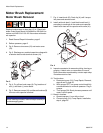
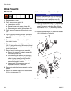
Removal
1. Relieve pressure; page 6.
2. Perform Storage More than 24 hours procedure in
Operation Manual 309973, 309974 or 309975.
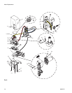
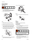
3. Fig. 8. Loosen clamp rod (20).
FIG.8
4. Release hopper quick-release clamp (28).
5. Disconnect pump module (A) from frame (35).
6. Remove five screws (12) and motor cover (18).
7. Fig. 10. Disconnect transducer connector (B) from
control board (38). Pull strain relief from bracket.
Thread transducer connector through bracket.
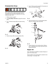
8. Fig. 9. Slowly rotate fan blade on back of motor until
connecting rod (45) near bottom of stroke.
FIG.9
9. Pry retaining spring (76) up on connecting rod (45).
Push pin (75) out with a screwdriver.
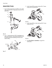
10. Fig. 10. Loosen retaining nut (27).
FIG.10
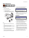
11. Fig. 11. Unscrew pump (31) from bearing housing
(34).
FIG.11
Repair
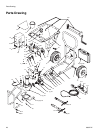
See page 20 for pump repair instructions.
Installation
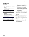
1. Fig. 17. Push piston rod (203) out of pump (31) 50
to 75 mm (2 to 3 inches).
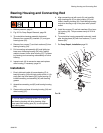
2. Fig. 11. Screw retaining nut (27) onto pump until it
stops. Screw pump (31) into bearing housing (34)
until pump stops. Unscrew pump until pump outlet is
13° from horizontal, but no more than one turn.
3. Tighten retaining nut (27).
4. Push pin (75) in with a screwdriver. Push retaining
spring (76) down on connecting rod (45).
5. Fig. 10. Connect transducer connector (B) to motor
control board (38).
WLD
$
WLD
I
If pin works loose, parts could break off due to force of
pumping action. Parts could project through the air and
result in serious injury or property damage. Make sure
pin and retaining spring are properly installed.
%
WLD


