Drive Housing
309977H 25
Drive Housing
Installation
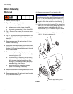
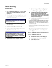
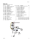
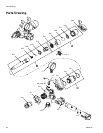
1. Fig. 21. Install thrust washers (10, 11, 14) on combi-
nation gear (29). Install combination gear in drive
housing (37).
2. Liberally apply bearing grease (supplied with combi-
nation gear) to all gear teeth and to drive housing
areas called out by note 1.
3. Align gears and push new drive housing straight
onto motor (33).
4. Install four screws (85) and washers (84).
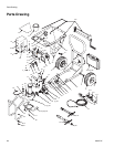
5. Install circuit board bracket (21) on drive housing
(37) with two screws (12).
6. Install bearing housing and pump assembly.
a. Align connecting rod with crank (G) and care-
fully align pins (H) in drive housing (37) with
holes in bearing housing (34).
b. Push bearing housing and pump assemblies
onto drive housing. Push connecting rod
assembly (45) and lightly tap lower front of bear-
ing housing with a plastic mallet to seat bearing
housing to drive housing (37).
c. Install bearing housing (34) with four screws (7)
and lock washers (6).
7. Thread transducer connector through circuit board
bracket. Push strain relief bushing (49) into circuit
board bracket (21). Connect transducer lead (E) to
control board (38).
8. Install two screws (86) and washers (84) into front of
drive housing.
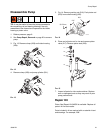
9. Fig. 21. Lay pump module horizontal. Install gear
housing base (25) with four washers (71) and
screws (90).
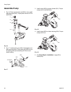
10. Fig. 6. Install motor cover (18) with five screws (12).
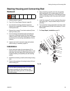
11. Fig. 5. Install pump module (A).
a. Connect pump module (A) onto frame (35).
b. Secure hopper quick-release clamp (28).
c. Tighten clamp rod (20).
NOTICE
When installing motor, carefully align gears to avoid
damaging mating parts.
NOTICE
Do not use bearing housing screws (7) to align or
seat bearing housing with drive housing. Align
these parts with locating pins (H), to avoid prema-
ture bearing wear.


