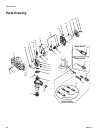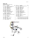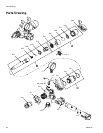
Drive Housing
24 309977H
Drive Housing
Removal
1. Relieve pressure; page 6.
2. Fig. 5. Remove pump module (A).
a. Loosen clamp rod (20).
b. Release hopper quick-release clamp (28).
c. Disconnect pump module (A) from frame (35).
3. Fig. 6. Remove Five screws (12) and motor cover
(18).
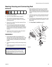
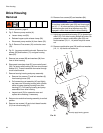
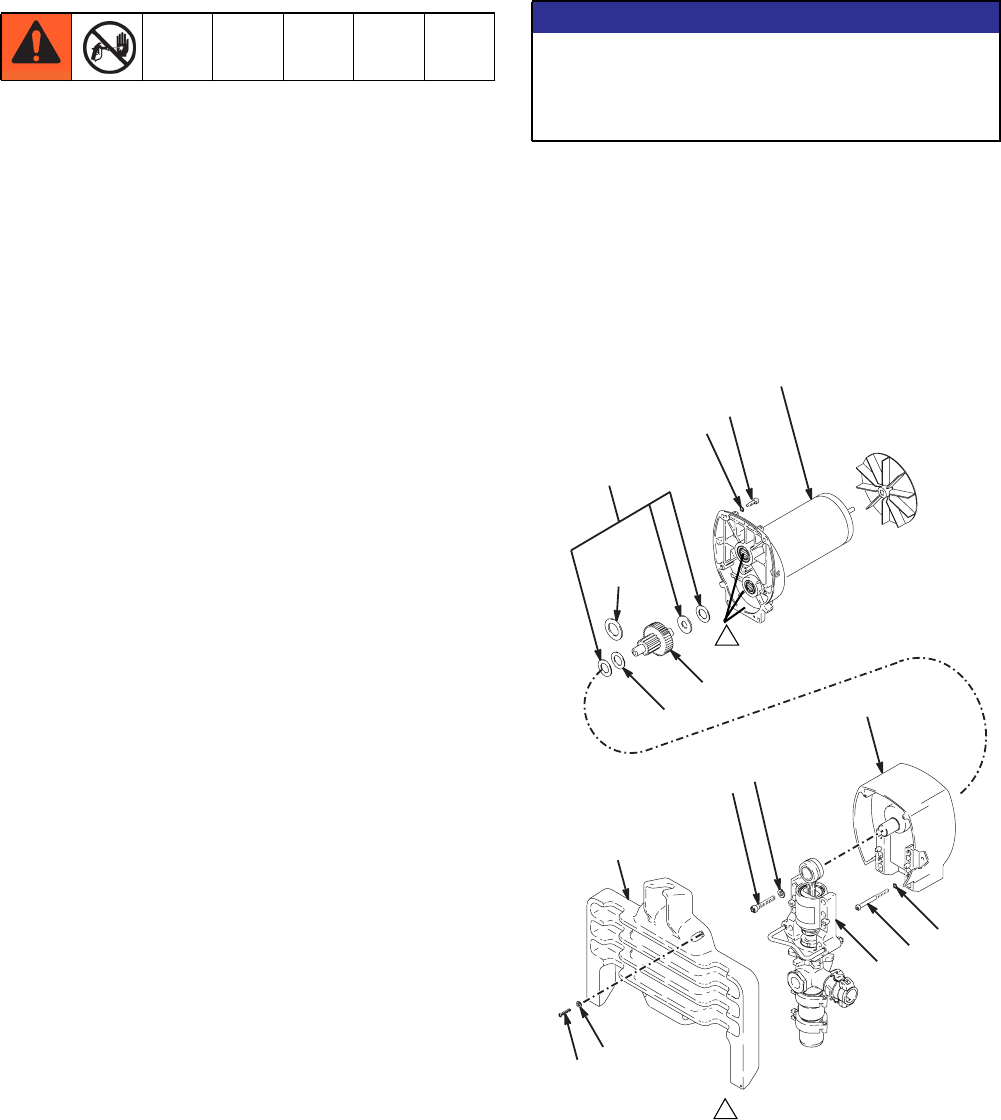
4. Fig. 21. Lay pump module horizontal. Remove four
screws (90) and washers (71) and gear housing
base (25).
5. Remove two screws (86) and washers (84) from
front of drive housing.
6. Disconnect transducer lead (E) from control board
(38). Pull strain relief bushing (49) from circuit board
bracket (21). Thread transducer connector through
circuit board bracket.
7. Remove bearing housing and pump assembly.
a. Remove four screws (7) and lock washers (6)
from bearing house (34)
b. Pull connecting rod assembly (45) and lightly
tap lower rear of bearing housing with a plastic
mallet to loosen bearing housing from drive
housing (37). Pull bearing housing and pump
assemblies from drive housing.
c. Inspect crank (G) for excessive wear and
replace drive housing, if necessary.
8. Return motor and drive housing assembly to vertical
position.
9. Remove two screws (12) and circuit board bracket
(21) from drive housing (37).
10. Remove four screws (85) and washers (84).
11. Lightly tap around drive housing (37) to loosen from
motor (33). Pull drive housing straight off motor. Be
prepared to support combination gear (29) and
thrust washers (10, 11, 14) which may also come
out.
12. Remove combination gear (29) and thrust washers
(10, 11, 14) that do not come out.
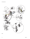
FIG.21
NOTICE
Do not drop combination gear (29) and thrust wash-
ers (10, 11, 14) when removing drive housing (37).
Combination gear and thrust washers may stay
engaged in motor front end bell or drive housing.
WLD
1
Liberally apply bearing grease
1


