


12 309063
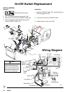
Spin Test
Setup
Electric Shock Hazard; page 6.
To check armature, motor winding and brush electrical
continuity:
1.
Relieve pressure; page 6.
2. Remove drive housing; page 24.
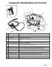
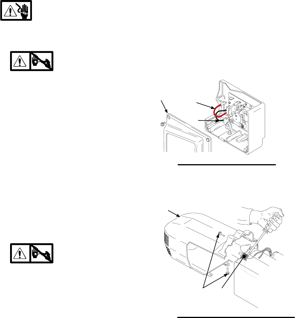
3. Fig. 7. Remove pressure control cover (39). Dis-
connect red and black motor leads from control
board.
4. Fig. 8. Remove motor shroud (74).
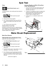
Armature Short Circuit Test
Quickly turn motor fan by hand. If no electrical shorts,
motor coasts two or three revolutions before complete
stop. If motor does not spin freely, armature is
shorted. Replace motor; page 25.
Armature, Brushes, and Motor Wiring Open
Circuit Test (Continuity)
1. Connect red and black motor leads together with
test lead. T urn motor fan by hand at about two
revolutions per second.
2. If uneven or no resistance, check for: broken brush
springs, brush leads, motor leads; loose brush
terminal screws, motor lead terminals; worn
brushes. Repair as needed; page 12.
3. If still uneven or no resistance, replace motor;
page 25.
9578A
Fig. 7
F
G
39
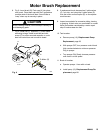
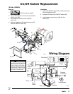
Motor Brush Replacement
Motor Brush Removal
Replace brushes worn to less than 1/4 in. (6 mm).
Check both sides. See Parts List 309064 for correct
brush kit for your series of sprayer .
1. Read General Repair Information; page 7.
2.
Relieve pressure; page 6.
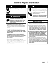
3. Fig. 8. Remove four screws (18) and motor
shroud (74).
4. Pry off two brush caps (A). Tag locations of red (+)
and black (--) motor leads. Cut tie wrap.
5. Fig. 5. Remove screw (C) and discard brush (B)
for motor with capacitor attached. Remove brush
leads from control box for motor without capacitor
attached.
(Continued on page 13)
TI0053
A
74
Fig. 8
18