


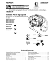
9309063
Troubleshooting
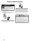
Relieve pressure; page 6.
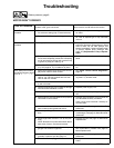
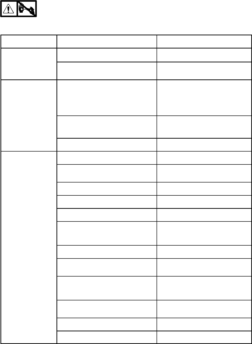
MOTOR WON’T OPERATE
TYPE OF PROBLEM
WHAT TO CHECK
If check is OK, go to next check
WHAT TO DO
When check is not OK refer to this column
Basic Fluid Pressure
Problems
1. Pressurecontrolknob setting.Motorwillnot run
if at minimum setting (fully counterclockwise).
1. Slowlyincreasepressuresettingtoseeifmo-
tor starts.
2. Spray tip or fluid filter may be clogged. 2. Relieve pressure and clear clog or clean fil-
ter; refer to separate gun or tip instruction
manual.
Basic Mechanical
Problems
1. Pump (13) frozen or hardened paint. 1. Thaw sprayer if water or water-based paint
has frozen in sprayer. Place sprayer in warm
area to thaw. Do not start sprayer until
thawed completely. If paint hardened (dried)
in sprayer, replace pump packings. See
page 26 (Displacement Pump Replace-
ment).
2. Displacement pump connecting rod pin (9a).
Pinmustbe completely pushed into connecting
rod (9) and retaining spring (9b) must be firmly
in groove of pump pin. See Fig. 18.
2. Pushpinintoplaceandsecurewithspringre-
tainer.
3. Motor (1). Remove drive housing assembly
(10). See page 24. Try to rotate fan by hand.
3. Replace motor (1) iffan won’tturn. See page
25.
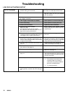
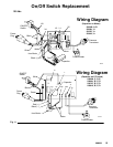
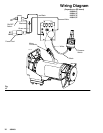
Basic Electrical Problems
SeeWiringDiagram,pages
1. Motorcontrolboard.Board shutsdown anddis-
plays error code on some models.
1. See Motor Control Board Diagnostics,
page 19.
g
g
,
p
g
15 to 18.
2. Electrical supply. Meter must read 100-- 130
VAC for 110--120 VAC models and 210 --255
VAC for 240 VAC models.
2. Reset building circuit breaker; replace build-
ing fuses. Try another outlet.
3. Extension cord. Check extension cord continu-
ity with volt meter.
3. Replace extension cord.
4. Sprayerpowersupply cord.Inspectfordamage
such as broken insulation or wires.
4. Replace power supply cord.
5. Fuse. Check replaceablefuseon controlboard. 5. Replace fuse after completing motorinspec-
tion.
6. Motor leadsare securelyfastened and properly
connected to control board.
6. Replace loose terminals; crimp to leads. Be
sure terminals are firmly connected.
Clean circuit board terminals. Securely re-
connect leads.
7. Motor thermal switch. Yellow motor leads must
have continuity through thermal switch.
7. Replace motor. See page 25, Motor Re-
placement.
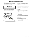
8. Brush cap missing or loose brush lead connec-
tions.
8. Install brush cap or replace brushes if leads
aredamaged. Seepage12,MotorBrushRe-
placement.
9. Brush length which must be 1/4 in.(6 mm)mini-
mum.
NOTE:Brushes donotwearat thesamerateon
both sides of motor. Check both brushes.
9. Replace brushes.See page 12, MotorBrush
Replacement.
10. Motor armature commutator for burn spots,
gouges and extreme roughness.
10. Remove motor and have motor shop resur-
face commutator if possible. See page 25,
Motor Replacement.
11.Motor armaturefor shorts using armaturetester
(growler) or perform spin test, page 12.
11.Replace motor. See page 25, Motor Re-
placement.
12. Pressurecontrolnotpluggedintocontrolboard. 12.Insertpressurecontrolconnectorintocontrol
board.