


20 309063
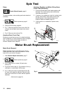
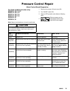
Pressure Control Repair
Motor Control Board
For these models and series on ly:
232900 A, B, C, D, E
232901 A, B, C, D
233797 A, B, C, D
233815 A, B, C, D
232903 A, B
232906 A, B
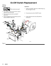
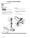
Removal
Refer to Fig. 10 and 11, 13 or 14 depending on sprayer
voltage.
1.
Relieve pressure; page 6.
2. Remove four screws (18) and cover (39).
3. Disconnect at motor control board (35):
D Filter board (X) (not 120 Vac sprayers).
D Four motor leads: two yellow , black (--)
and red (+).
D T wo line voltage leads.
D Lead (D) from potentiometer.
D Lead (E) from transducer .
4. Remove five screws (36) and circuit board (35).
Installation
1. Clean pad on rear of motor control board. Apply
small amount of thermal compound 073019 to pad.
2. Fig. 10. Install motor control board (35) with five
screws (36).
3. Connect to motor control board (35):
D Lead (E) to transducer.
D Lead (D) to potentiometer.
D T wo line voltage leads.
D Four motor leads: two yellow , black (--)
and red (+).
D Filter board (X) (not 120 Vac sprayers).
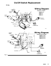
4. Bundle and tie all loose wires so none lay in con-
tact with inductor coil on filter board (not 120 Vac
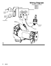
sprayers). See Wiring Diagram CAUTION,
Fig. 13 or 14.
5. Install cover (39) with four screws (18).