


21309063
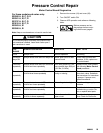
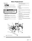
Pressure Control Repair
For these models and series on ly:
232900 A, B, C, D, E
232901 A, B, C, D
233797 A, B, C, D
233815 A, B, C, D
232903 A, B
232906 A, B
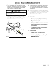
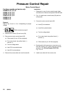
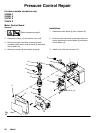
Pressure Control Transdu cer
Removal
Refer to Fig. 10 and 11, 13 or 14 depending on sprayer
voltage.
1.
Relieve pressure; page 6.
2. Remove four screws (18) and cover (39).
3. Disconnect lead (E) from motor control
board (35).
4. Remove two screws (22) and filter housing (45).
5. Thread transducer lead plastic connector down
through transducer grommet (28).
6. Remove pressure control transducer (52) and
packing o-ring (51) from filter housing.
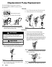
Installation
1. Install packing o-ring (51) and pressure control
transducer (52) in filter housing (45). Torque to
30--35 ft-lb.
2. Thread transducer lead plastic connector up
through transducer grommet (28).
3. Install filter housing (45) with two screws (22).
4. Connect lead (E) to motor control board (35).
5. Install cover (39) with four screws (18).
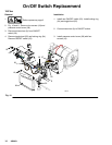
Pressure Adjust Potentiometer
Removal
Refer to Fig. 10 and 11, 13 or 14 depending on sprayer
voltage.
1.
Relieve pressure; page 6.
2. Remove four screws (18) and cover (39).
3. Disconnect all leads from motor control board (35).
4. Remove five screws (36) and board (35)
5. Remove potentiometer knob (27), sealing shaft nut
(33) and pressure adjust potentiometer (26).
Installation
1. Install pressure adjust potentiometer (26), sealing
shaft nut (33) and potentiometer knob (27).
a. T urn potentiometer fully clockwise.
b. Install knob at full clockwise position.
2. Install board (35) with five screws (36).
3. Connect all leads to motor control board (35).
4. Install cover (39) with four screws (18).