18 308-125
Removing
a
n
d I
nstallin
g a D
isplacemen
t P
ump
Removal
WARNING
To
reduce the risk of serious injury
, always follow
the
Pressure Relief Procedure
on page 8 before
repairing the sprayer
.
1. Flush
the sprayer
. Remove the suction
hose, if used.
WARNING
To
reduce the risk of pinching or amputating a
finger
, keep your fingers away from the area of the
connection rod and pin while jogging the engine.
2.
Start the engine. Jog the pressure control ON/OFF
switch
until the connecting link stops near the bottom
of
the stroke and is fully exposed. See Fig. 13. Shut
off
the engine.
3. Unscrew
the collar
of the power supply cord and un
-
plug
the cord from the pressure control. See Fig. 14.
4. Relieve
the pressure
.
5. Remove the outlet hose. Slightly loosen the two
mounting
screws. See Fig. 13.
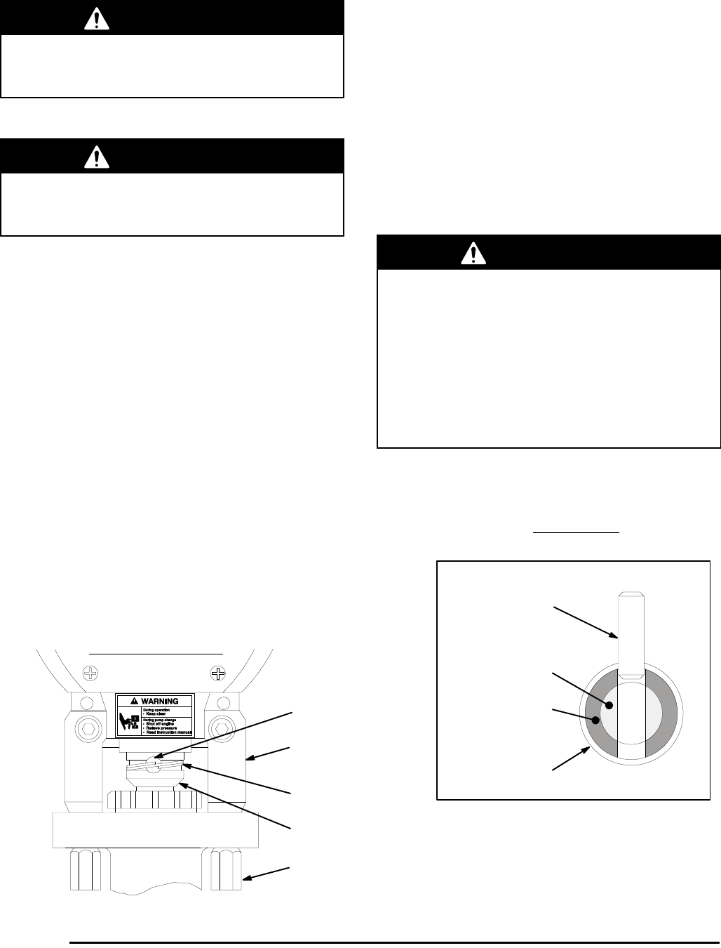
6. Use a small screwdriver to push in the connecting
link
pin just until you can gently pry the retaining ring
up from the back of the connecting link. Then push
the
pin in so it falls out the back.
7. Remove the two mounting screws while supporting
the
weight of the pump with your free hand.
Installation
1. Push
the pin just barely into the connecting link, but
not
into the mating hole of the displacement pump.
2. Pull the displacement rod out of the pump 2 to 3 in.
(50–75 mm).
3. Align the flats of the pump piston rod and the pump
outlet.
Lift the pump into position and gently push on
the pin while moving the pump slightly until the pin
slips into the hole. Be sure the retaining ring snaps
down
over the end of the pin.
WARNING
Be sure the retaining spring is firmly in the groove
of the connecting link, all the way around, to pre
-
vent it from working loose due to vibration. See Fig.
13.
If the pin work loose, it or other parts could break
of
f due to the force of the pumping action and
result in serious injury or property damage, includ
-
ing damage to the pump, connecting link or bearing
housing.
Procedure continued on page 19.
BACK
OF PUMP
FRONT OF PUMP
CUTAWA
Y VIEW
SHOWS HOW PIN GOES
THROUGH CONNECTING ROD
FRONT VIEW OF PUMP AND
SPRA
YER CONNECTING LINK
0407
PIN
BEARING HOUSING
RETAINING RING
CONNECTING LINK
MOUNTING SCREWS
T
orque to
20 ft–lb (27 N.m)
PUMP PIST
ON ROD
CONNECTING LINK
PIN
RETAINING RING
Fig.
13


