20 308-125
Displacement
Pump
Repair
Kit
1A
Packing Repair Kit, Part No. 224–523, is
available.
Use
all the parts in the kit for the best results.
2 Parts
included in the kit are marked with an asterisk
in
the text and drawings. For example, 408*.
Reassemble the pump
NOTE: Refer to Fig. 13 for reassembly except where
noted.
NOTE: Grease
all packings and o–rings before installing
them.
1. Install the ball guide (409), ball (411*) and intake
housing
(410) in the lug nut (421).
2.
Place new o–rings (404*) on the cylinder (405).
3. On the piston seat (422), install the u–cup seal
(408*), lips down. Install the female gland (412*).
With
the lips of the v–packings facing up, alternately
install
the leather (407*)
and poly packings (413*). In
-
stall
the male gland (406*).
4. Install the nut (414) on the piston seat (422). Hand
tighten
the nut very firmly
.
NOTE: If
you disassembled the piston rod
(401) and pis
-
ton
housing (416), clean the threads
thoroughly
.
Apply red LoctiteR and torque to 35–50 ft–lb
(47–68
N.m).
5. Apply
Loctite
R
green (supplied in the repair kit) to the
piston
seat (422) threads. Install the ball (415*).
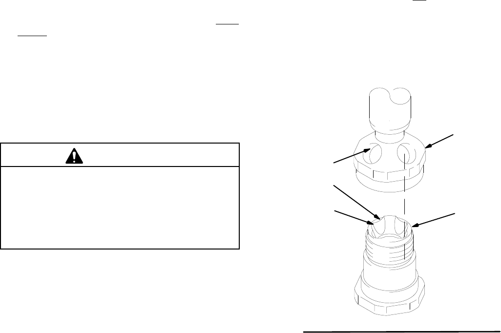
CAUTION
Before assembling the piston, not that the top of the
piston seat (422) has four flutes (B) and that the
piston housing (416) has four holes (A). T
ogether
these flutes and holes provide the fluid flow path.
Failure to align the parts properly
, as instructed in
Step 6, will result in poor pump performance.
6. Back off the piston housing just until the holes and
flutes (B) mentioned in the CAUTION are perfectly
aligned,
and the tips
(B) are not visible when you look
through
the holes (A). See Fig 20–1. Screw the pis
-
ton housing (416) down to the nut (414) and torque
to
90–125 ft–lb (122–170 N.m).
7. From the top of the pump housing (417), install the
male
gland (403). With the lips of the v–packings
fac
-
ing down, alternately install the leather packings
(418*), and poly packings (402*). Install the female
gland
(419*).
8. Screw
in the packing nut (420) loosely
. It will be
tight
-
ened
after the pump is installed and operating.
9. Grease the o–rings on the cylinder (405). Slide the
cylinder
into the bottom of the pump housing (417).
10. Grease the piston rod (401) and piston packings.
Slide
the piston rod assembly into the bottom of the
cylinder so it extends out of the piston housing 2–3
in.
(50–75 mm). Be careful not to damage any pack
-
ings.
11. Align the holes in the top of the piston rod with the
pump
outlet.
NOTE: If
you push the piston rod too far out of the pump
housing, using a hard rubber mallet (ONLY!) to
tap
it down.
If
the piston rod does not extend out far enough,
remove
the foot valve and tap the piston up.
12.
Install the intake valve housing and tighten firmly
.
13. Install
the pump and prime
it. Check the packing nut
(20)
and tighten it just enough to prevent leakage.
422
416
HOLE
FLUTE
TIP
055
Fig. 16


