


308-125 31
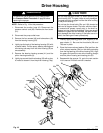
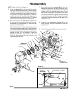
Reassembly
NOTE:
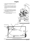
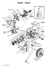
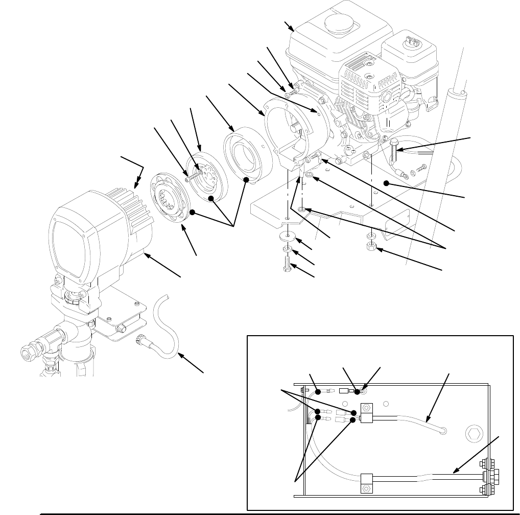
Refer to Fig. 31 for Steps 5–9.
5. Place
the
engine (45)
on the cart. Align the mount
-
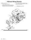
ing holes. Guide the engine wire (A) and wiring har
-
ness
(69) through the mounting
plate grommets (8).
Install
the screws (42) and nuts (43) and torque to 15
ft–lb (20 N.m). Install the capscrews (5), lockwash-
ers
(6) and washer (7) from under the engine
mount
-
ing
plate
to secure the clutch housing (17). Connect
the
like-colored wires as shown in the Detail A.
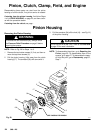
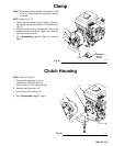
6. Be sure the face of the rotor (9a) and the field (10)
is free of all oil and contaminants. Install the rotor,
lockwashers
(2) and capscrews (4). T
orque the cap
-
screws
to 7 ft–lb (9.5 N.m).
After installing the rotor (9a), pull the engine recoil
rope
to assure that the engine turns freely and there
is
no friction between the rotor (9a) and the field (10).
If
there is friction, loosen the setscrews (16) and re
-
position the field (10) as necessary. Tighten the
setscrews oppositely and evenly to 25 in–lb
(2.8
N.m). Also make sure there are no burrs on the
outside
edge of the rotor
.
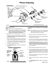
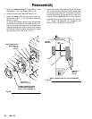
7. Be sure the face of the armature (9b) is clean. As-
semble
the armature to the shaft in
the pinion hous
-
ing (C). A retaining ring located within the armature
makes it difficult to assemble these parts. For the
best
results, first
engage a few splines of both parts,
then use a screwdriver to gently push the retaining
ring
into the armature, and then engage the remain
-
ing
splines. Push the armature onto the shaft until it
contacts the ring.
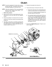
8. Assemble the drive/pinion housing (C) to the
clutch housing, using the capscrews (3) and lock-
washers (2).
9.
Connect the cord set (62) to the pressure control.
TORQUE
T
O
7 ft–lb (9.5 N.m)
43
45
3
2
17
9a
12
4
9b
19n,19k
42
C
FACES
MUST
BE
CLEAN
DETAIL
A
TORQUE
T
O
15 ft–lb (20.4 N.m)
10
7
6
5
69
0403
B
0405
62
16
VIEW FROM UNDER ENGINE MOUNTING PLA
TE
8
A
T
O FIELD
FROM ENGINE
RED
62
BLACK
WHITE
GREEN W/
RED COVER
Fig.
31