


308-125 19
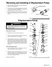
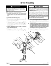
Removing
a
n
d I
nstallin
g A D
isplacemen
t P
ump
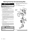
4. Check
the back of the bearing housing to be sure the
parts
are installed properly
.
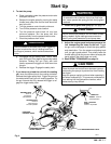
5. Lift
the pump to align the mounting holes and install
the mounting screws. IMPORTANT – torque the
screws
to 20 ft-lb (27 N.m). See Fig. 13.
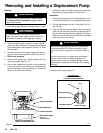
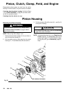
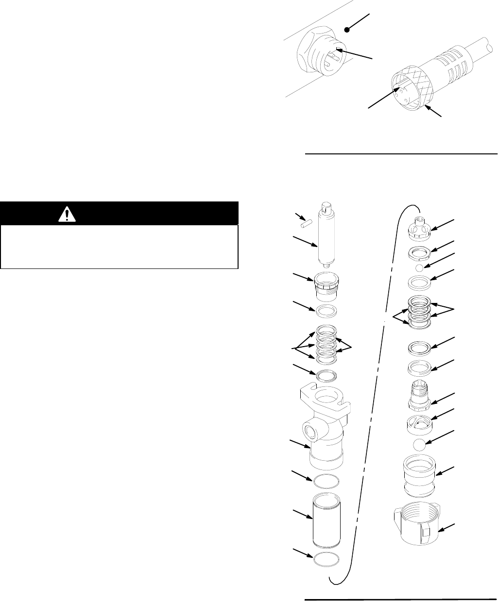
6. Plug
in the power cord so the notch in the collar and
the
tab in the socket align. Screw on the collar
. See
Fig. 14.
0408
PRESSURE CONTROL
TAB
NOTCH
COLLAR
Fig.
14
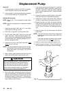
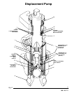
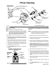
Displacement
Pump
WARNING
To
reduce the risk of serious injury
, always follow
the
Pressure Relief Procedure
on page 8 before
repairing the sprayer
.
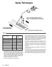
Disassemble the pump
1
See page 18 for how to remove the pump.
2 Use a hard rubber mallet on the tabs of the lug nut
(421)
to loosen the foot valve housing.
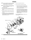
3
Disassemble the pump, but do not disassemble the
piston
rod (401) from the piston housing (416)
unless
one
of those needs to be replaced. Due to the high-
strength
Loctite
r
used at the joint of these two parts,
the joint must be heated before disassembly. Refer
to
Fig. 15.
Clean and inspect all parts
1 Use a compatible solvent to thoroughly clean all
parts
and remove all traces of sealant.
2. Inspect the parts, including seats, for nicks and
scratches. Replace worn or damaged parts as they
cause the packings to wear more quickly and/or re-
sult
in poor pump performance.
Continued on page 20.
421
409
411*
410
422
408*
416
415*
406*
413*
412*
414
401
420
*419
418**402
*403
417
*404
*404
*405
423
0412
*407
Fig. 15