


308-548 15
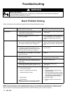
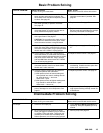
Basic Problem Solving
TYPE OF PROBLEM WHA
T T
O CHECK
If check is OK, go to next check
WHA
T T
O DO
When check is not OK, refer to this column
Electrical
(continued)
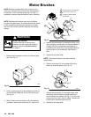
5. Check
motor armature commutator for burn
spots, gouges and extreme roughness. Re
-
move motor cover and brush inspection plates
to check. See page 20.
5.
Remove motor and have motor shop
resurface commutator if possible. See
page 26.
6.
Check motor armature for shorts using arma
-
ture tester (growler) or perform motor test.
See page 18.
6.
Replace motor
. See page 26.
7. Check
leads from pressure control and motor to
motor
start board (47) to be sure they are se
-
curely fastened and properly mated.
7.
Replace loose terminals; crimp to leads.
Be sure male terminal blades are straight
and firmly connected to mating part.
8.
Check motor start board (47) by substituting
with a good board. See page 27.
CAUTION:
Do not perform this check until mo
-
tor armature is determined to be good. A bad
motor armature can burn out a good board.
8.
Replace board. See page 27.
9. Check power supply cord (50). Disconnect
black and white power cord terminals; connect
volt
meter to these
leads. Plug in sprayer
. Meter
should
read 105–125V
AC. Unplug sprayer
.
9.
Replace power supply cord. See page
27.
10. Check ON/OFF switch (52). Disconnect the
motor start board (47) and switch and connect
volt meter between exposed terminal on switch
and power cord’
s white wire. Plug in sprayer
and turn
ON
. Meter should read 105–125V
AC
T
urn of
f and unplug sprayer
.
10.
Replace ON/OFF switch. See page 27.
11.
Check motor thermal cutout switch. Connect
ohmmeter between motor
’
s red leads. Meter
should read 1 ohm maximum.
11.
Allow motor to cool. Correct cause of
overheating. If switch remains open after
motor cools, replace motor
.
12.
Remove pressure control (64) and check mi
-
croswitch operation with ohmmeter:
(1)
With pressure knob at lowest setting and
stem pushed into control, readings should
be: white & black = 1 ohm max.
white & red = open.
(2)
With pressure knob at highest setting,read
-
ings should be: white & black = open;
white & red = 1 ohm max.
12.
Replace pressure control. See page 30.
13.
Check pressure transducer (29) for hardened
paint or damaged or worn components. See
page 31.
13.
Replace transducer
. See page 31. Thor
-
ough system flushing will help extend life
of transducer
.
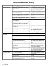
Intermediate Problem Solving
TYPE OF PROBLEM WHA
T T
O CHECK
If check is OK, go to next check
WHA
T T
O DO
When check is not OK refer to this column
Low output
1.
Check for worn spray tip. 1.
Follow
Pressure Relief Procedure
then
replace tip. See your separate gun or
tip
manual.
2.
Be sure pump does not continue to stroke
when gun trigger is released. Plug in and turn
on sprayer
. Prime with paint. T
rigger gun mo
-
mentarily
, then release and lock safety latch.
Relieve pressure, turn of
f and unplug sprayer
.
2.
Service pump. See page 22.