


24 308-548
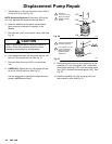
Displacement
Pump Repair
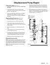
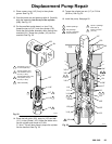
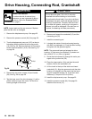
3. Tighten
the nut (1
10) onto the piston valve (108) to
2 in-lb (0.23 N.m). See Fig. 20.
NOTE: Note the alignment
of the piston (108) to the
nut (1
10). Maintain this alignment through Step 8.
4.
Clean all residue from the piston valve threads.
Apply one strip of adhesive, supplied, to the
threads.
5.
Place the ball (109*) on the piston valve (108). See
Fig. 20.
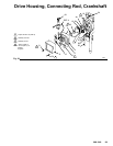
CAUTION
Step 6, tightening the piston valve into the rod, is
critical. Follow the procedure carefully to avoid
damaging the packings by overtightening.
6.
Hand tighten the valve into the piston rod just until
the nut (1
10) contacts the rod. See Fig. 21.
7.
Place the flats of the rod (107) in a smooth jaw
vise.
8. CAREFULLY
tighten the nut (1
10) against the pis
-
ton rod to 30 ft-lb (40 N.m). See Fig. 21.
Use two wrenches to maintain the alignment men
-
tioned in
NOTE
below Step 3.
Fig. 20
1
2
01070
Torque
to
5 in–lb (0.57 N.m)
107
*109
110
108
Apply one strip of
sealant to these
threads
2
Fig.
21
1
2
01071
108
110
107
Torque
nut against rod
to 30 ft–lb (4o N.m)
Do not allow nut (110)
to move relative to
piston (108) when
tightening piston
against rod.
1
2
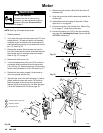
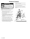
9. Stack
these parts one at a time into the top of the
manifold (101): the male gland (106*), alternately
three plastic packings (104*) with two leather pack
-
ings (105*), and then the female gland (103*). See
Fig. 23.
10.
Install the packing nut (102) and plug (124), but
leave loose for now
. See Fig. 23.