


28 308-548
Drive
Housing, Connecting Rod, Crankshaft
WARNING
INJECTION
HAZARD
T
o reduce the risk of serious injury
,
whenever you are instructed to relieve
pressure, follow the
Pressure Relief
Procedure
on page 9.
NOTE:
Inspect parts as they are removed. Replace
parts that are worn or damaged.
1.
Remove the displacement pump. See page 22.
2.
Remove the pressure control (64). See page 30.
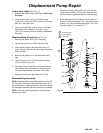
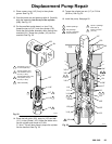
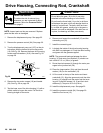
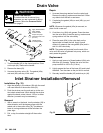
3. T
urn the displacement pump rod (107) so the pin
hole aligns with the bottom drive housing screw
(19). See Fig. 28. Remove the three drive housing
screws and lockwashers (19,6). Also see Fig. 29
on page 29.
107
19,6
Fig. 28
01074
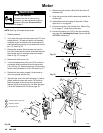
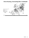
4.
Remove the two motor screws (19) and handle
(24). See Fig. 29 on page 29.
5. T
ap the lower rear of the drive housing (1
1) with a
plastic mallet to loosen the motor
. Pull the drive
housing straight of
f the motor
.
CAUTION
Do not allow the gear (16) to fall; it may stay
attached to the drive housing or to the motor
.
Do
not lose the thrust balls (1
1a or 4a) or let them
fall
between
the gears, which will damage the drive
housing
if not removed. The balls, which are heav
-
ily covered with grease, usually stay in the gear
re
-
cesses,
but could be dislodged. If the balls are not
in
place, the bearings will wear prematurely
.
6.
Remove and inspect the crankshaft (12) and the
connecting rod (15).
7.
Install the connecting rod.
8.
Lubricate the inside of the drive housing bearing
with SAE non-detergent oil. Pack the roller bearing
and gears with the grease supplied.
NOTE:
The gears and bearings between the drive
housing (1
1) and motor front end bell (C) should con
-
tain a total of 3 fl. oz. (29 cc) of grease.
9.
Route the wire harness (A) through the motor pas
-
sages to the junction box (59).
10.
Place the large washer (12a) and then the small
washer (12b) on the crankshaft (12).
11.
Lift the crank to the top of the stroke and insert
crankshaft (12). Align the gears and push the drive
housing (1
1) straight onto the motor and the locat
-
ing pins. Install the screws (19, 5) and their lock
-
washers (6). T
orque to 80 in–lb (9 N.m).
12.
Install the displacement pump. See page 22.
13.
Install the pressure control (64). See page 30.
Install the front cover (13).