


18 308-548
Motor
T
est
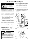
WARNING
INJECTION
HAZARD
T
o reduce the risk of serious injury
,
whenever you are instructed to relieve
pressure, follow the
Pressure Relief
Procedure
on page 9.
For checking armature, motor winding and brush elec
-
trical continuity
.
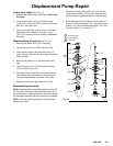
Setup
Remove the drive housing. See page 28. This is to
ensure that any resistance you notice in the armature
test is due to the motor and not to worn gears in the
drive housing.
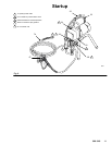
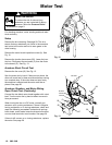
Remove the motor brush inspection covers (A).
See
Fig. 12.
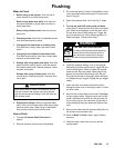
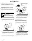
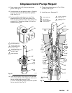
Remove the junction box screws (56). Lower the junc
-
tion box. Disconnect the two leads (C) from the motor
to the board (47). See Fig. 13.
Armature Short Circuit Test
Remove
the fan cover (B). See Fig. 12.
Spin the motor fan by hand. If there are no shorts, the
motor will coast two or three revolutions before coming
to a complete stop. If the motor does not spin freely
,
the armature is shorted and the motor must be re
-
placed. See page 26.
Armature, Brushes, and Motor Wiring
Open Circuit Test (Continuity)
Connect
the two black motor leads together with a test
lead. T
urn the motor fan by hand at about two revolu
-
tions per second.
When turning the fan on a DC motor, normally you
sense an even, pulsing resistance. If there is irregular
turning resistance, or no turning resistance, check and
repair the following as needed: broken brush springs,
brush leads, motor leads; loose brush terminal screws
or motor lead terminals; worn brushes. See page 20.
If there is still uneven or no turning resistance, replace
the motor
. See page 26.
A
B
Fig. 12
04652
04720
47
MOTOR
BLACK/
WHITE
BLACK
C
59
RED
Fig. 13
56
89
58